background image


- 32 -


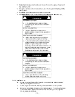
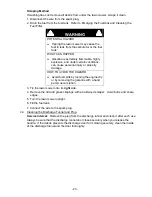
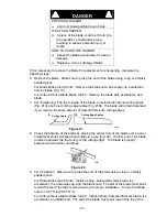
1.  Run the engine to warm the oil. 

WARNING


POTENTIAL HAZARD 

  Oil may be hot after engine has been run. 

WHAT CAN HAPPEN 

  Contact with hot oil can cause severe 

personal injury. 

HOW TO AVOID THE HAZARD 

  Avoid contacting the hot engine oil when 

you drain it. 


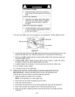
2.  Stop the engine and wait for all moving parts to stop. 


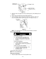
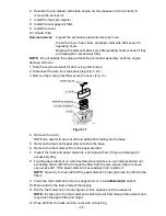
3.  Disconnect the wire from the spark plug (Fig. 5 & 7). 


4.  Drain the engine oil. 


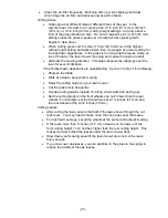
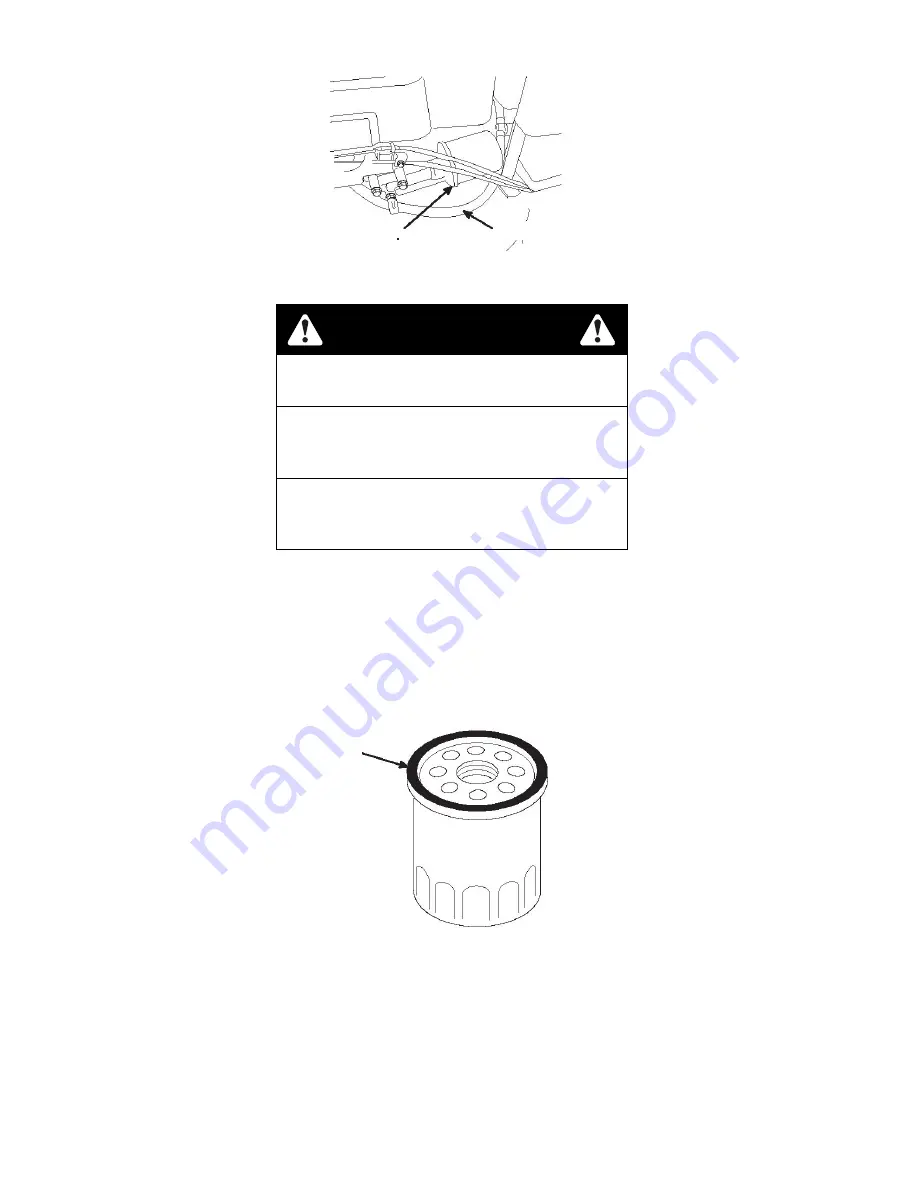
5.  Place a rag under the oil filter to catch any oil that may leak out as you remove the 

filter. 


6.  Remove the oil filter. 


7.  Use your finger to coat the gasket on the new filter with clean engine oil. 


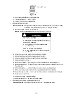
8.  Install the new filter and hand tighten it 2/3 turn only. 


9.  Fill the crankcase to the Full line on the dipstick with fresh oil. 


10. Connect the wire to the spark plug. 


11. Run the engine for about 3 minutes. 


12. Stop the engine, wait for all moving parts to stop, and check for oil leakage around 

the filter. 


13. Add oil to compensate for the oil in the oil filter.   

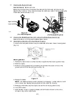
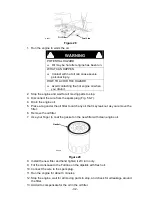
Figure 28 

Oil Filter

Fuel Line 

Gasket 

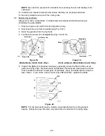
Figure 29 

G0227 

G0228 

Summary of Contents for Metro 21 Series

Page 1: ...ealer or distributor If you need to order replacement parts from your dealer always give the model number and serial number of your mower as well as the part number description and quantity of the part needed The Serial No plate is located on the top of the mower deck on the right hand corner of the machine For ease of ordering and reference wesuggest that you record the information requested in t...

Page 2: ...er opening Keep away from eyes and skin Never siphon by mouth IMPORTANT When the mower is used or operated on any California forest brush or grass covered land a working spark arrester must be attached to the muffler If not the operator is violating state law Section 4442 Public Resource Code To acquire a spark arrester for your unit see your Engine Service Dealer This spark ignition system compli...

Page 3: ...bmitting the Exmark Parts Plus order to Exmark by 3 00 p m central time the Distributor pays for the part and freight 3 Exmark being unable to ship the part and the Exmark parts order is received by 3 00 p m central time Exmark pays for the part and freight 4 If the part does not arrive overnight due to the shipper UPS the shipper pays for the freight and Exmark pays for the part The following res...

Page 4: ...maintain its maximum efficiency and promote safe operation If additional information is needed or should you require trained mechanic service contact your authorized Exmark equipment dealer or distributor All Exmark equipment dealers and distributors are kept informed of the latest methods of servicing and are equipped to provide prompt and efficient service in the field or at their service statio...

Page 5: ...3 4 4 Cleaning the Discharge Tunnel and Plug 23 24 4 5 Servicing the Air Filter 24 26 4 6 Maintaining the Blade 26 28 4 7 Cleaning the under the belt cover 28 4 8 Cleaning the Blade Brake Clutch Shield 28 29 4 9 Emptying the Fuel Tank and Cleaning the Fuel Filter 29 30 4 10 Lubricating the Pivot Arms 30 4 11 Adjusting the Self Propelled Drive 30 4 12 Servicing the Spark Plug 30 31 4 13 Changing th...

Page 6: ...or serious injury CAUTION Black lettering Yellow background Indicates a potentially hazardous situation which if not avoided MAY result in minor or moderate injury 1 2 TRAINING 1 2 1 Regard the Exmark mower as a piece of power equipment andteach this regard to all who operate this unit 1 2 2 Read the instructions carefully Familiarize yourself with the controls and the proper use of the equipment ...

Page 7: ...g trousers Do not operate equipment when barefoot or when wearing open sandals 1 3 4 Thoroughly inspect the area where the equipment is to be used and remove all stones sticks wires bones and other foreign objects which may damage the equipment or cause personal injury to the operator or bystanders WARNING POTENTIAL HAZARD Engine exhaust contains carbon monoxide which is an odorless deadly poison ...

Page 8: ...it out of the reach of children Add fuel before starting the engine Never remove the cap of the fuel tank or add fuel when engine is running or when the engine is hot Never fill the fuel tank so that the gasoline level rises above a level that is 1 2 1 3 cm below the bottom of the filler neck to allow for gasoline expansion and prevent fuel spillage If fuel is spilled DO NOT attempt to start the e...

Page 9: ...ill gasoline containers inside a vehicle or on a truck or trailer bed because interior carpets or plastic truck bed liners may insulate the container and slow the loss of any static charge When practical remove gas powered equipment from the truck or trailer and refuel the equipment with its wheels on the ground If this is not possible then refuel such equipment on a truck or trailer from a portab...

Page 10: ...soline in an enclosed trailer 1 4 OPERATION Although hazard control and accident prevention are partially dependent upon the design and configuration of the equipment these factors are also dependent upon the awareness concern prudence and proper training of the personnel involved in the operation transport maintenance and storage of the equipment It is essential that all Operator Safety Mechanism...

Page 11: ...dden turns or rapid speed changes Progressively greater care is needed as the slope increases Watch for ditches holes rocks dips and rises that change the operating angle as rough terrain could overturn the machine Remove or mark obstacles such as rocks tree limbs etc from the mowing area Tall grass can hide obstacles Use extreme care with grass catchers or attachments These can change the stabili...

Page 12: ...properly 1 4 18 Grass catcher components are subject to wear damage and deterioration which could expose moving parts or allow objects to be thrown Frequently check the components and replace them with the manufacturer s recommended parts when necessary 1 4 19 Be aware of the mower discharge and direct discharge away from others 1 4 20 Do Not operate mower under the influence of alcohol or drugs 1...

Page 13: ...4 New safety signs may be obtained from your authorized Exmark equipment dealer or distributor or from Exmark Mfg Co Inc 1 6 5 Safety signs can be affixed by peeling off the backing to expose the adhesive surface Apply only to a clean dry surface Smooth to remove any air bubbles 1 6 6 Familiarize yourself with the following safety signs and instruction labels They are critical to the safe operatio...

Page 14: ...ION Top RH Surface of Mower Deck PART NO 104 8585 LOCATION Top LH Surface of Mower Deck For Self Propelled Units PART NO 74 1970 LOCATION Top Surface of Trans Cover For Units with a Blade Brake Clutch PART NO 103 6328 LOCATION Top Surface of Throttle Control For Units without a Blade Brake Clutch PART NO 103 6327 LOCATION Top Surface of Throttle Control ...

Page 15: ... stop 2 5 TRANSMISSION 2 5 1 3 speeds forward Speed range 1 st 2 0 mph 3 2 km h 2 nd 2 9 mph 4 6 km h 3 rd 4 1 mph 6 6 km h 2 6 DECK 2 9 1 Cutting Width 21 53 cm 2 9 2 Blade Brake When the blade engagement control is moved to the disengaged position a friction brake pad stops the rotation of the blades 2 9 3 Cutting Height Adjusts in 1 2 64 cm increments from 75 to 3 25 1 9 cm 8 3 cm 2 7 DIMENSION...

Page 16: ... handles as shown in Figure 1 The lever is used to control engine speed Moving the lever to the full forward Choke position will place the lever in the choke position The choke aids in starting a cold engine Moving the throttle control forward will increase engine speed and moving it to the rear will decrease engine speed For units with a Blade Brake Control The throttle choke control also include...

Page 17: ...ing and during transport to and from the job Rotate the valve 1 4 turn clockwise to shut off fuel Rotate the valve 1 4 turn counter clockwise to turn on fuel 3 2 PRE START 3 2 1 Refer to Section 4 Maintenance and perform all of the necessary inspection and maintenance steps 3 2 2 Fill the Fuel Tank with Gasoline See Section 1 3 Preparation section for safety information regarding the proper way to...

Page 18: ... these fuels can damage the engine s fuel system NOTE Do not use gasoline that has been stored since the last mowing season or longer 1 Clean around the fuel tank cap Fig 5 6 FIGURE 5 Honda Engines Only FIGURE 6 Kawasaki Engines Only 2 Remove the cap from the tank 3 Fill the fuel tank with unleaded gasoline to within 1 4 to 1 2 inch 6 to 13 mm from the top of the tank Do not fill into the filler n...

Page 19: ...ly 6 When the engine starts move the throttle control to the Fast position and set the ground speed control as desired NOTE If the engine fails to start after 3 pulls repeat steps 3 6 3 3 3 Stopping the Engine For units without a Blade Brake Clutch Release the blade control bail Both the engine and the blade should stop within 3 seconds For units with a Blade Brake Clutch Release the blade control...

Page 20: ...inor injury keep hands clear of the blade control lever when the blade control bail is released 3 3 6 Using the Discharge Tunnel 1 Stop the engine and wait for all moving parts to stop 2 Insert the plug Refer to Section 3 4 Installing the Discharge Plug 3 To remove the plug move the discharge door handle rearward and lift up the spring clip on the bottom of the plug When the plug is unlocked pull ...

Page 21: ... will continue to rotate when you release the blade control bail WHAT CAN HAPPEN Contact with the blade could occur causing serious injury HOW TO AVOID THE HAZARD Check the BBC operation before each use Never use the BBC equipped lawn mower with an inoperative safety system Take your lawn mower to an Authorized Service Dealer for repair if the safety system fails to operate properly Test Using the...

Page 22: ...for all movement to stop before adjusting the cutting height Do not put your fingers under the housing when adjusting the cutting height 1 Pull the wheel height adjustment lever toward the wheel Fig 9 and move it to the desired setting 2 Release the wheel height adjustment lever and set it securely in the notch 3 Adjust all the wheels to the same cutting height setting 3 3 9 Using the Grass Bag Oc...

Page 23: ...ss bag could allow small stones and other similar debris to be thrown in the operator s or bystander s direction WHAT CAN HAPPEN Thrown objects can result serious personal injury or death to the operator or bystanders HOW TO AVOID THE HAZARD Check the grass bag frequently If it is damaged install a new Exmark replacement bag Cut the grass until the bag is full NOTE Do not overfill the bag Removing...

Page 24: ...the discharge area stop the engine and gently move the discharge door handle back and forth until you can close the door completely If you still cannot close the door remove the obstruction with a stick not your hand DANGER POTENTIAL HAZARD If the discharge door does not close completely the lawn mower could throw objects WHAT CAN HAPPEN Thrown objects can result serious personal injury or death t...

Page 25: ...ilization If the finished lawn appearance is unsatisfactory try one or more of the following Sharpen the blade Walk at a slower pace while mowing Raise the cutting height on your lawn mower Cut the grass more frequently Overlap cutting swaths instead of cutting a full swath with each pass Set the cutting height on the front wheels one notch lower than the rear wheels For example set the front whee...

Page 26: ...stem 100 Hours For Kawasaki Engines Change the oil filter Inspect the spark plug and replace it if necessary Clean the cooling system remove grass clippings debris or dirt from the engine air cooling fins and starter Clean the system more frequently in dirty or high chaff conditions Lubricate the gear case For units with a Blade Brake Clutch Adjust the blade brake cable Service the wheels 250 Hour...

Page 27: ... Fig 14 Washing Method 1 Position the lawn mower on a flat concrete or asphalt surface near a garden hose 2 Start the engine 3 Hold the running garden hose a handle level and direct the water to flow on the ground just in front of the right rear tire Fig 15 4 Engage the blade NOTE The blade will draw in water and wash out clippings Let the water run until you no longer see clipping being washed ou...

Page 28: ...OW TO AVOID THE HAZARD Avoid fuel spills by running the engine dry or by removing the gasoline with a hand pump never siphon 3 Tip the lawn mower onto its right side 4 Remove the dirt and grass clippings with a hardwood scraper Avoid burrs and sharp edges 5 Turn the lawn mower upright 6 Fill the fuel tank 7 Connect the wire to the spark plug 4 4 Cleaning the Discharge Tunnel and Plug Service Inter...

Page 29: ...scharge tunnel door is locked in place 4 5 Servicing the Air Filter For Kawasaki Units Service Interval Clean the foam pre cleaner every 25 operating hours Replace the paper air filter once every season or every 300 operating hours more frequently in dusty conditions NOTE Do not operate the engine without the air filter assembly extreme engine damage will occur 1 Stop the engine and wait for all m...

Page 30: ...ent dirt and debris from falling into the base 5 Remove the foam and paper elements from the base 6 Remove the foam element from the paper element 7 Inspect the foam and paper elements and replace them if they are damaged or excessively dirty 8 Tap the paper element on a hard surface several times or use compressed air not exceeding 30 psi 207 kPa through the filter from the wire screen side to re...

Page 31: ... spark plug Fig 5 7 3 Drain the gasoline from the fuel tank 4 Tip the lawn mower onto its right side Fig 18 and 19 5 Inspect the Blade for sharpness and wear especially where the flat and the curved parts meet Fig 20A Because sand and abrasive material can wear away the metal that connects the flat and curved parts of the blade check the blade before using the lawn mower If you notice a slot or we...

Page 32: ...utting edge radius Fig 21B The blade will remain balanced if you remove the same amount of material from both cutting edges 8 Check the balance of the blade by placing the center hole of the blade over a nail or screwdriver shank clamped horizontally in a vise Fig 22 If either end of the blade rotates downward file that end not the cutting edge The blade is properly balanced when neither end drops...

Page 33: ...Cleaning under the belt cover Self Propelled Models Only 1 Stop the engine and wait for all moving parts to stop 2 Disconnect the wire from the spark plug Fig 5 7 3 Remove the bolts that secure the belt cover to the lawn mower housing Fig 23 4 Lift off the cover and brush out all the debris around the belt area 5 Install the belt cover 6 Connect the wire to the spark plug 4 8 Cleaning the Blade Br...

Page 34: ... shield Rotate the tabs 180 back into position Tighten the nuts to the bolts on tabs to secure the BBC shield to the deck 9 Install the blade the accelerator the anti scalp cup and the two blade nuts 10 Turn the lawn mower upright 11 Connect the wire to the spark plug 4 9 Emptying the Fuel Tank and Cleaning the Fuel Filter Kawasaki Units Only Service Interval Clean the fuel filter element every 10...

Page 35: ...es not self propel or has a tendency to creep forward when the control bar is released adjust the wheel drive control knob on the rear of the gear box 1 Close the door in the lawn mower housing and remove the grass bag 2 If the lawn mower does not self propel rotate the control knob clockwise 1 2 turn to tighten the belt If the lawn mower creeps forward rotate the knob 1 2 turn counterclockwise to...

Page 36: ...nd wait for all moving parts to stop 3 Disconnect the wire from the spark plug Fig 5 7 4 Place a suitable drain pan under the dipstick oil drain 5 Clean around the dipstick 6 Remove the dipstick by rotating the cap counterclockwise and pulling it out 7 Raise the left side of the lawn mower to drain the oil form the dipstick fill tube into the drain pan 8 After draining the oil return the lawn mowe...

Page 37: ...nder the oil filter to catch any oil that may leak out as you remove the filter 6 Remove the oil filter 7 Use your finger to coat the gasket on the new filter with clean engine oil 8 Install the new filter and hand tighten it 2 3 turn only 9 Fill the crankcase to the Full line on the dipstick with fresh oil 10 Connect the wire to the spark plug 11 Run the engine for about 3 minutes 12 Stop the eng...

Page 38: ...ides Fig 31 4 Pull the cable to remove the slack but do not put tension on the spring 5 Tighten the screw to lock the adjustment in place 6 Connect the wire to the spark plug For Self Propelled Units without a Blade Brake Clutch 3 Loosen the nut on the cable bracket Fig 31 4 Insert a 3 16 to 1 4 in 5 to 6 mm object between the brake control lever and the handle 5 Turn the cable adjuster on the bra...

Page 39: ...s or bolts 1 3 20 x 1 5 in and non locking nuts loosely secure the wheel halves together Mount the screws or bolts in the opposing holes 5 Check the alignment of all parts and tighten the screws alternating from side to side for a uniform fit until the wheel halves are drawn together 6 Install the 2 cap screws and 2 locknuts previously removed in the remaining holes in the wheel halves and tighten...

Page 40: ...g Fig 5 7 3 Using an oil can add about one tablespoon of oil to the crankcase through the spark plug hole 4 Slowly rotate the engine several times using the starter rope to distribute the oil 5 Install the spark plug but do not connect the wire to the spark plug 5 3 General Storage Information 1 Clean the lawn mower housing Refer to Section 4 3 Cleaning the Underside of the Lawn Mower Housing 2 Cl...

Page 41: ...sists contact an Authorized Service Dealer 2 The throttle lever is not in the Choke position 2 Move the throttle lever to the Choke position 3 The wire is not connected to the spark plug 3 Connect the wire to the spark plug Engine does not start 4 The spark plug is pitted fouled or the gap is incorrect 4 Check the spark plug and adjust the gap if necessary Replace the spark plug if it is pitted fo...

Page 42: ...ne mounting bolts are loose 4 Tighten the engine mounting bolts 1 All four wheels are not at the same height 1 Place all four wheels at the same height 2 The blade is dull 2 Sharpen and balance the blade 3 You are mowing in the same pattern repeatedly 3 Change the mowing pattern Uneven cutting pattern 4 The underside of the lawn mower deck contains clippings and debris 4 Clean the underside of the...

Page 43: ...with the Service Dealer s analysis or with the assistance provided contact us at Exmark Customer Service Department The Exmark Warranty Company 2101 Ashland Avenue Beatrice NE 68310 402 223 6375 or service exmark com Owner s Responsibilities The Exmark turf equipment including any defective part must be returned to an authorized Exmark service dealer within the warranty period This warranty extend...

Page 44: ... 39 NOTES ...

Page 45: ... 40 NOTES ...

Page 46: ... 41 NOTES ...

Page 47: ... 42 SERVICE RECORD Date Description of Work Done Service Done By ...

Page 48: ...AC QUICK DISPOSAL SYSTEM WALK BEHIND ACCESSORIES GRASS CATCHER MICRO MULCH SYSTEM STEERABLE SULKY SULKY HITCH KIT TURF STRIPER STANDON WARNING The engine exhaust from this product contains chemicals known to the State of California to cause cancer birth defects or other reproductive harm 1997 2007 EXMARK MFG CO INC PART NO 109 4826 Rev A INDUSTRIAL PARK BOX 808 402 223 6300 BEATRICE NE 68310 FAX 4...

Reviews: