background image

1.  SAFETY 


1.1 SAFETY ALERT SYMBOL


This SAFETY ALERT SYMBOL


 is used both in this manual and on the machine to 

identify important safety messages which must be followed to avoid accidents.  This symbol 
means: 

ATTENTION!  BECOME ALERT! 

YOUR SAFETY IS INVOLVED!


The safety alert symbol appears above information which alerts you to unsafe actions or 
situations and will be followed by the word 

DANGER

WARNING

, or 

CAUTION.


DANGER

: White lettering / Red background.  Indicates an imminently hazardous situation 

which, if not avoided, 

WILL

 result in death or serious injury. 


WARNING

: Black lettering / Orange background.  Indicates a potentially hazardous situation 

which, if not avoided, 

COULD

 result in death or serious injury.  


CAUTION

: Black lettering / Yellow background.  Indicates a potentially hazardous situation 

which, if not avoided, 

MAY

 result in minor or moderate injury. 


1.2 TRAINING


1.2.1  Regard the Exmark mower as a piece of power equipment and teach this regard to all 

who operate this unit.  This machine is capable of amputating hands and feet and 
throwing objects.  Failure to observe the following safety instructions could result in 
serious injury or death. 

1.2.2  Read the instructions carefully.  Familiarize yourself with the controls and the proper 

use of the equipment.  If the operator(s) or mechanic(s) can not read English it is the 
owner’s responsibility to explain this material to them. 

1.2.3  Do not allow operation of this machine by untrained personnel.  Never allow children, 

or teenagers to use the mower.  Only allow responsible adults who are familiar with 
the instructions, to operate this machine.  Local regulations may restrict the age of the 
operator. 

1.2.4  Data indicates operators age 60 years and above are involved in a large percentage of 

riding mower related injuries.  These operators should evaluate their ability to operate 
the riding mower safely enough to protect themselves and others from serious injury. 

1.2.5  Avoid mowing while people, especially children, or pets, are nearby. Keep in mind that 

the operator or user is responsible for accidents or hazards occurring to other people 
or their property. 


1.3 PREPARATION


1.3.1  Evaluate the terrain to determine what accessories and attachments are needed to 

properly and safely perform the job.  Only use accessories and attachments approved 
by Exmark. 

1.3.2  Always wear eye protection.  The use of personal protective equipment for the ears, 

feet, and head is also recommended. 


For Exmark Mower Parts Call 606-678-9623 or 606-561-4983

www.mymowerparts.com

Summary of Contents for Phazer

Page 1: ...rom your dealer always give the model number and serial number of your equipment as well as the part number description and quantity of the part needed The Serial No plate is located on right side of the console For ease of ordering and reference we suggest record the information requested in the following identification table that you Place Model No and Serial No Label Here Included in Literature...

Page 2: ...Never siphon by mouth IMPORTANT When the mower is used or operated on any California forest brush or grass covered land a working spark arrester must be attached to the muffler If not the operator is violating state law Section 4442 Public Resource Code To acquire a spark arrester for your unit see your Engine Service Dealer This spark ignition system complies with Canadian ICES 002 Ce système d a...

Page 3: ... Exmark by 3 00 p m central time the Distributor pays for the part and freight 3 Exmark being unable to ship the part and the Exmark parts order is received by 3 00 p m central time Exmark pays for the part and freight 4 If the part does not arrive overnight due to the shipper UPS the shipper pays for the freight and Exmark pays for the part The following restrictions apply The Exmark Parts Plus P...

Page 4: ...mote safe operation If additional information is needed or should you require trained mechanic service contact your authorized Exmark equipment dealer or distributor All Exmark equipment dealers and distributors are kept informed of the latest methods of servicing and are equipped to provide prompt and efficient service in the field or at their service stations They carry ample stock of service pa...

Page 5: ...und Drive System 14 2 8 Tires Wheels 14 2 9 Cutting Deck 14 15 2 10 Dimensions 15 2 11 Torque Requirements 15 3 OPERATION INSTRUCTIONS 3 1 Controls 16 18 3 2 Pre Start 18 3 3 Mowing 18 19 3 4 Transporting 20 21 4 MAINTENANCE ADJUSTMENTS 4 1 Periodic Maintenance 22 30 4 2 Adjustments 30 33 5 WASTE DISPOSAL 5 1 Motor Oil Disposal 34 5 2 Battery Disposal 34 6 TROUBLE SHOOTING 6 1 Mower Pulls Left or ...

Page 6: ...Read the instructions carefully Familiarize yourself with the controls and the proper use of the equipment If the operator s or mechanic s can not read English it is the owner s responsibility to explain this material to them 1 2 3 Do not allow operation of this machine by untrained personnel Never allow children or teenagers to use the mower Only allow responsible adults who are familiar with the...

Page 7: ...ection when operating this machine 1 3 3 While mowing always wear substantial footwear and long trousers Do not operate equipment when barefoot or when wearing open sandals 1 3 4 Thoroughly inspect the area where the equipment is to be used and remove all stones sticks wires bones toys and other foreign objects which may damage the equipment or cause personal injury to the operator or bystanders F...

Page 8: ... cap of the fuel tank or add fuel when engine is running or when the engine is hot Never fill the fuel tank so that the gasoline level rises above a level that is 1 2 below the bottom of the filler neck to allow for gasoline expansion and prevent fuel spillage Replace gas cap and tighten securely If fuel is spilled on clothing change clothing immediately If fuel is spilled DO NOT attempt to start ...

Page 9: ...tatic charge When practical remove gas powered equipment from the truck or trailer and refuel the equipment with its wheels on the ground If this is not possible then refuel such equipment on a truck or trailer from a portable container rather than from a gasoline dispenser nozzle If a gasoline dispenser nozzle must be used keep the nozzle in contact with the rim of the fuel tank or container open...

Page 10: ...uilding or room 1 4 CHILDREN 1 4 1 Tragic accidents can occur if the operator is not alert to the presence of children Children are often attracted to the machine and the mowing activity Never assume that children will remain where you last saw them 1 4 2 Keep children out of the mowing area and in the watchful care of a responsible adult other than the operator 1 4 3 Be alert and turn machine off...

Page 11: ...m muffler and engine area Install and maintain in working order a spark arrester before using equipment on forest covered grass covered or brush covered unimproved land WARNING POTENTIAL HAZARD Hands feet hair clothing or accessories can become entangled in rotating parts WHAT CAN HAPPEN Contact with rotating parts can cause traumatic amputation or severe lacerations HOW TO AVOID THE HAZARD DO NOT...

Page 12: ... transport to and from the job When parked inside a building 1 5 14 This mower was designed for one operator only Never carry passengers and keep all others away from mower during operation 1 5 15 Never operate the mower with defective guards shields or covers Always have safety shields guards switches and other devices in place and in proper working condition 1 5 16 DO NOT mow with the discharge ...

Page 13: ...s or water This area can be dangerous see Figure 1 FIGURE 1 1 6 4 Progressively greater care is needed as the slope increases 1 6 5 Do not try to stabilize the machine by putting your foot on the ground 1 6 6 Always avoid sudden starting or stopping on a slope If tires lose traction disengage the blades and proceed slowly down the slope 1 6 7 Avoid sudden starts when mowing uphill Mower may tip ba...

Page 14: ... to 12 4 volts Note To prevent damage due to freezing battery should be fully charged before putting away for winter storage 1 8 4 Keep engine engine area and hydraulic pump area free from accumulation of grass leaves excessive grease or oil and other debris which can accumulate in these areas These materials can become combustible and may result in a fire Allow engine to cool completely before st...

Page 15: ...ands away from pinhole leaks or nozzles that eject high pressure hydraulic fluid Use cardboard or paper not your hands to find hydraulic leaks Safely relieve all pressure in the hydraulic system by placing the motion control levers in neutral and shutting off the engine before performing any work on the hydraulic system 1 9 COMMERCIAL USER SETUP 1 9 1 On the 34 deck three of the four 5 16 18 x 3 4...

Page 16: ...B71 4 2004 Safety Standard for Commercial Turf Care Equipment Safety Specifications 1 9 4 For Non Commercial Consumer Users IMPORTANT DO NOT make the changes outlined in Steps 1 9 1 1 9 3 These changes are not in compliance with ANSI B71 1 2003 Safety Standard for Consumer Turf Care Equipment Walk Behind Mowers and Ride On Machines with Mowers Safety Specifications 1 9 5 For non commercial users l...

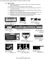
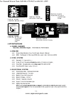
Page 17: ...the following safety signs and instruction labels They are critical to the safe operation of your Exmark commercial mower PART NO 1 403005 LOCATION Left and Right Corners of Mower Deck PART NO 1 303508 LOCATION Bottom Right Corner of Mower Deck PART NO 109 2465 LOCATION Left of Center on Mower Deck Under Floor Pan PART NO 1 513746 LOCATION On Rear Guard PART NO 109 2862 LOCATION RH Frame Panel PAR...

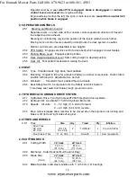
Page 18: ...ernator 2 4 2 Charging Capacity 13 amps 2 4 3 Battery Type BCI Group U1 2 4 4 Battery Voltage 12 Volt 2 4 5 Polarity Negative Ground 2 4 6 Fuses Two 20 amp blade type 2 4 7 Safety Interlock System PTO must be disengaged brake engaged and motion control levers out neutral lock to start engine It is not necessary for the operator to be in the seat to start the engine PART NO 109 2494 LOCATION Center...

Page 19: ... to battery and other components Held in tilted position with lanyard Adjustable fore and aft 2 6 3 Armrests Standard foam padded flip up armrests 2 6 4 Seat Safety Switch Incorporated into the Safety Interlock System Time delay seat switch eliminates rough ground cut outs 2 7 HYDROSTATIC GROUND DRIVE SYSTEM 2 7 1 Hydrostatic Drive Two Hydro Gear ZT2800 Integrated drive systems 2 7 2 Hydraulic Oil...

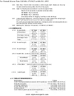
Page 20: ...35 0 in 89 0 cm 47 4 in 120 4 cm Discharge chute down 44 0 in 111 8 cm 54 7 in 139 0 cm 2 10 2 Overall Length 34 Deck 44 Deck 70 0 in 177 8 cm 70 0 in 177 8 cm 2 10 3 Overall Height 34 Deck 44 Deck 39 0in 99 1 cm 39 0in 99 1 cm 2 10 4 Tread Width center to center of tires widthwise 34 deck 44 deck Drive Wheels 26 5 in 67 3 cm 35 0 in 88 9 cm Front Casters 29 0 in 73 7 cm 29 0 in 73 7 cm 2 10 5 Whe...

Page 21: ...ment of the left lever forward will cause the left drive wheel to rotate in a forward direction Movement of the right lever forward will cause the right drive wheel to rotate in a forward direction To stop forward travel pull the levers back to the neutral position To turn left while moving forward move the left lever back toward neutral to slow the left drive wheel To turn right while moving forw...

Page 22: ...1 6 Brake Lever Located on left side of the console The brake lever engages a parking brake stopping the drive wheels Pull the lever up and rearward to engage the brake Push the lever forward and down to disengage the brake The unit must be tied down and brake engaged when transporting 3 1 7 Ignition Switch Located right of center on the console The ignition switch is used to start and stop the en...

Page 23: ...f the filler neck to allow for fuel expansion and prevent fuel spillage 3 2 2 Make sure you understand the controls their locations their functions and their safety requirements 3 2 3 Refer to Maintenance Section 4 and perform all the necessary inspection and maintenance steps 3 3 MOWING 3 3 1 Open fuel shut off valve The fuel shut off valve is located under the seat in the fuel line between the l...

Page 24: ...ower deck and discharge area before engaging PTO IMPORTANT Operator must be in seat before the PTO can be engaged Set throttle to midway position Pull outward on the switch to the ROTATE position Accelerate to full throttle to begin mowing 3 3 4 Stopping PTO Set the throttle to the midway position Push in on the switch to the STOP position stopping the PTO 3 3 5 Stopping Engine Bring unit to a ful...

Page 25: ...ot have proper turn signals lights reflective markings or a slow moving vehicle emblem These items are required to drive on a public street or roadway WHAT CAN HAPPEN Driving on a street or roadway without such equipment is dangerous and can lead to accidents causing personal injury Driving on a street or roadway without such equipment may also be a violation of State laws and the operator may be ...

Page 26: ...the tractor frame extends back between the rear wheels and serves as a stop for tipping backward Having a full width ramp provides a surface for the frame members to contact if the unit starts to tip backward If it is not possible to use one full width ramp use enough individual ramps to simulate a full width continuous ramp Ramp should be long enough so that the angles between the ramp and the gr...

Page 27: ...D Allow the engine to cool completely before service or making repairs around the engine area 4 1 PERIODIC MAINTENANCE 4 1 1 Check engine oil level Service Interval Daily a Stop engine wait for all moving parts to stop and engage parking brake Make sure unit is on a level surface b Check with engine cold c Clean area around dipstick Remove dipstick and wipe oil off Reinsert the dipstick Screw dips...

Page 28: ...zing battery should be fully charged before putting away for winter storage a Check the voltage of the battery with a digital voltmeter Locate the voltage reading of the battery in the table below and charge the battery for the recommended time interval to bring the charge up to a full charge of 12 6 volts or greater IMPORTANT Make sure the negative battery cables are disconnected and the battery ...

Page 29: ...ine wait for all moving parts to stop and remove key Engage parking brake b Lift deck and secure in raised position as stated in Section 4 1 4 c Inspect blades and sharpen or replace as required d Re install the blades if they were removed in the following order See Fig 7 1 Install bushing through blade with bushing flange on bottom grass side of blade 2 Install bushing blade combo into spindle 3 ...

Page 30: ...disengaged and the left motion control lever in starter must not crank repeat again with the right lever in then with both levers in starter must not crank b Check kill circuits Run engine at one third throttle disengage parking brake and raise off of seat but do not get off of machine engine must stop after approx 1 2 second has elapsed seat has time delay kill switch to prevent cut outs on rough...

Page 31: ...he hose for future use d Replace the oil filter as per the Engine Owner s Manual Clean around oil filter and unscrew filter to remove Before reinstalling new filter apply a thin coating of oil on the surface of the rubber seal Turn filter clockwise until rubber seal contacts the filter adapter then tighten filter an additional 2 3 to 3 4 turn e Clean around oil fill cap and remove cap Fill to spec...

Page 32: ...l Bearings 1 2 yearly 4 Front Caster Pivots 1 2 yearly See 4 1 13 Section c for special lubrication instructions on the front caster pivots and Section 4 1 14 for special lubrication instructions on the front caster wheel hubs c Lubricate front caster pivots once a year Remove hex plug and cap Thread grease zerk in hole and pump with grease until it oozes out around top bearing Remove grease zerk ...

Page 33: ...l caster bolt and tighten nut fully IMPORTANT To prevent seal and bearing damage check the bearing adjustment often Spin the caster tire The tire should not spin freely more than 1 or 2 revolutions or have any side play If the wheel spins freely adjust torque on spacer nut until there is a slight amount of drag 4 1 15 Lubricate brake handle pivot Service Interval 160 hrs a Stop engine wait for all...

Page 34: ...of vent reinstall plug Torque plugs to 180 in lbs 244 N m Continue to add oil until it reaches the FULL COLD line on the expansion reservoir FIGURE 9 f Raise the rear of machine up and support with jack stands or equivalent support just high enough to allow drive wheels to turn freely g Start engine and move throttle control ahead to 1 2 throttle position Disengage parking brake 1 With the bypass ...

Page 35: ...octite RC 609 or RC 680 or Fel Pro Pro Lock Retaining I or Retaining II are used on the following a Fuel tank studs where studs are inserted into tank 4 1 22 Mobil HTS grease or food grade antisieze is used in the following locations a Between the cutter housing spindle and bearings b Between the cutter housing spindle and sheave c Under top cutter housing bearing guard 4 1 23 Dielectric grease is...

Page 36: ...e b Stop engine wait for all moving parts to stop and remove key Engage parking brake c Check tire pressure in drive tires Proper inflation pressure for drive tires is 13 psi 90 kPa Proper inflation for caster tires is 16 psi 110 kPa Adjust if necessary d Set anti scalp rollers to top holes or remove completely for this adjustment e Lower the deck to the 1 1 2 3 8 cm height position Place two 1 1 ...

Page 37: ... or in the bottom two holes to decrease the height of the levers a Align the levers front rear position With the levers in the neutral position loosen the hardware and adjust the levers sliding and or tilting the lever s forward or backward until properly aligned and tighten hardware See Figure 13 FIGURE 13 b If the ends of the levers hit against each other while in the drive position levers rotat...

Page 38: ...he spring extension should measure 6 12 6 25 15 5 15 9 cm in length as shown in Figure 15 Loosen the bolt and slide the bracket to adjust the length and retighten the hardware If the specified length cannot be achieved by adjusting the bracket replace the belt This should be checked in the 3 position FIGURE 15 c Belt tension and spring adjustment should be checked during the break in period and re...

Page 39: ...er operating and is being scrapped take the battery to a local certified recycling center If no local recycling is available return the battery to any certified battery reseller 6 TROUBLE SHOOTING 6 1 MOWER PULLS LEFT OR RIGHT WITH LEVERS FULLY FORWARD a Check air pressure in tires 13 psi drive b Check motion control linkage adjustment See Section 4 2 6 6 2 MOWER CUTS UNEVENLY a Check air pressure...

Page 40: ...steps attempt to start the engine If it does not start contact your authorized Exmark service dealer IMPORTANT It is essential that all operator safety mechanisms be connected and in proper operating condition prior to mower use When a problem occurs do not overlook the simple causes For example starting problems could be caused by an empty fuel tank The following table lists some of the common ca...

Page 41: ...36 7 KAWASAKI ELECTRICAL DIAGRAM For Exmark Mower Parts Call 606 678 9623 or 606 561 4983 www mymowerparts com ...

Page 42: ...s or with the assistance provided contact us at Exmark Customer Service Department The Exmark Warranty Company 2101 Ashland Avenue Beatrice NE 68310 402 223 6375 or service exmark com Owner s Responsibilities The Exmark turf equipment including any defective part must be returned to an authorized Exmark service dealer within the warranty period This warranty extends only to turf equipment operated...

Page 43: ... instructions must be warranted for the warranty period of two years If any such part fails during the period of warranty coverage it must be repaired or replaced by Exmark Manufacturing Company Any such part repaired or replaced under the warranty must be warranted for a time not less than the remaining warranty period B Any warranted part that is scheduled only for regular inspection in the writ...

Page 44: ...39 NOTES For Exmark Mower Parts Call 606 678 9623 or 606 561 4983 www mymowerparts com ...

Page 45: ...40 NOTES For Exmark Mower Parts Call 606 678 9623 or 606 561 4983 www mymowerparts com ...

Page 46: ...41 SERVICE RECORD Date Description of Work Done Service Done By For Exmark Mower Parts Call 606 678 9623 or 606 561 4983 www mymowerparts com ...

Page 47: ...42 For Exmark Mower Parts Call 606 678 9623 or 606 561 4983 www mymowerparts com ...

Page 48: ... ACCESSORIES GRASS CATCHER MICRO MULCH SYSTEM STEERABLE SULKY SULKY HITCH KIT TURF STRIPER STANDON WARNING The engine exhaust from this product contains chemicals known to the State of California to cause cancer birth defects or other reproductive harm 2006 EXMARK MFG CO INC PART NO 109 4354 Rev A INDUSTRIAL PARK BOX 808 402 223 6300 BEATRICE NE 68310 FAX 402 223 5489 ALL RIGHTS RESERVED PRINTED I...

Reviews: