background image

Maintenance

Important:

Replace the foam element if it

is torn or worn.

3.

Lightly oil the foam element using new engine oil
and squeeze out any excess oil.

Paper Element:

1.

Lightly tap the element on a flat surface to remove
dust and dirt.

2.

Inspect the element for tears, an oily film, and
damage to the seal.

Important:

Do not clean the paper element

with pressurized air or liquids, such as
solvent, gas, or kerosene. Replace the paper
element if it is damaged or cannot be cleaned
thoroughly.

3.

Replace the paper element if it is damaged.

Installing the Air Cleaner

1.

Install the foam pre-cleaner element over the
paper element.

Note:

Ensure that you do not damage the

elements.

2.

Install the air cleaner elements onto the air cleaner
base.

3.

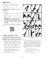
Install the cover and secure it with the retaining
clamps (see Figure 41).

Checking the Engine Oil Level

Service Interval: Before each use or daily

Important:

Do not overfill the crankcase with oil

and run the engine; engine damage may result.

1.

Park machine on level ground, move the motion
control levers out to engage the parking brake,
disengage the blade control switch, stop engine,
and remove key. Wait for all moving parts to stop
before leaving the operator’s position.

2.

Make sure the engine is stopped, level, and is cool
so the oil has had time to drain into the sump.

3.

To keep dirt, grass clippings, etc., out of
the engine, clean the area around the oil fill
cap/dipstick before removing it.

4.

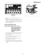
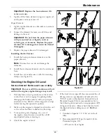
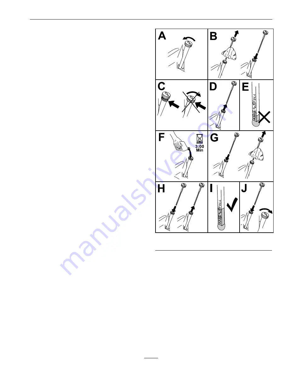
Check the engine oil level.

g336929

Figure 43

5.

If the level is low, wipe off the area around the oil
fill cap, remove cap/dipstick and add oil to the
“FULL” mark on the dipstick. Exmark 4-Cycle
Premium Engine Oil is recommended; refer to
the following information for an appropriate API
rating and viscosity. Always check the level with
the dipstick before adding more oil.

Do Not

overfill.

Crankcase Capacity: 1.9 L (64 oz) with oil
filter

Recommended Oil Type: Exmark 4-Cycle
Premium Engine Oil

– API service SJ or higher

43


Summary of Contents for QUEST 346

Page 1: ...QUEST For Serial Nos 408 644 346 Higher Part No 4505 333 Rev A ...

Page 2: ... is equipped with a spark arrester as defined in Section 4442 maintained in effective working order or the engine is constructed equipped and maintained for the prevention of fire To acquire a spark arrester for your unit see your Engine Service Dealer For all models that do not have Exmark engines please refer to the engine manufacturer s information included with the machine For models with Exma...

Page 3: ...uals If additional information is needed or should you require trained mechanic service contact your authorized Exmark equipment dealer or distributor All Exmark equipment dealers and distributors are kept informed of the latest methods of servicing and are equipped to provide prompt and efficient service in the field or at their service stations They carry ample stock of service parts or can secu...

Page 4: ...0 Side Discharge 30 After Operation 31 Transporting 31 Operating Tips 33 Maintenance 34 Maintenance Safety 34 Recommended Maintenance Schedule s 35 Periodic Maintenance 35 Lubrication 36 Engine Safety 36 Engine Maintenance 36 Servicing an Exmark Engine 37 Servicing a Kohler Engine 42 Cleaning the Blower Housing 47 Fuel System Maintenance 47 Electrical System Maintenance 47 Charging the Battery 47 ...

Page 5: ...rowing objects Always follow all safety instructions to avoid serious personal injury or death Read understand and follow all instructions and warnings in the Operator s Manual and on the machine engine and attachments All operators and mechanics should be trained If the operator s or mechanic s can not read this manual it is the owner s responsibility to explain this material to them other langua...

Page 6: ... or removed keep the deflector in place 2 Cutting dismemberment hazard of hand or foot mower blade stay away from moving parts decal99 3943 99 3943 For Models with 50 or 54 Inch Mower Decks 1 Belt routing 2 Engine decal105 7015 105 7015 For Models with 34 Inch or 42 Inch Mower Decks 1 Belt routing decal130 0765 130 0765 1 Read the Operator s Manual 3 Remove the key from the ignition and read the O...

Page 7: ...ector discharge cover or grass collection system in place 4 Pinch hazard stay away from moving parts keep shields in place decal136 5596 136 5596 For Models with 50 Inch Decks 1 Check the tire pressure every 25 operating hours 4 Check the tire pressure every 25 operating hours 2 Engine oil 5 Read the Operator s Manual before performing maintenance 3 Check the tire pressure every 25 operating hours...

Page 8: ...ng brake decal139 2395 139 2395 1 Parking brake 4 Neutral 2 Fast 5 Reverse 3 Slow 6 Traction controls decal139 5892 139 5892 For Models with 54 Inch Deck 1 Height of cut decal142 5854 142 5854 1 Bypass lever position for pushing the machine 2 Bypass lever position for operating the machine 8 ...

Page 9: ...ur Meter 1 Fast 4 Choke Off 2 Slow 5 Optional hour meter accessory 3 Choke On decal142 5862 142 5862 Models with Hour Meter 1 Fast 3 Choke On 2 Slow 4 Choke Off decal142 5864 142 5864 decalptosymbols PTO Switch Symbols 1 PTO disengage 2 PTO engage 9 ...

Page 10: ...s and shields in place 5 Ramp hazard when loading onto a trailer do not use dual ramps only use a singular ramp wide enough for the machine and that has an incline less than 15 degrees back up the ramp in reverse and drive forward off the ramp 3 Thrown object hazard Keep bystanders away pick up debris before operating and keep the deflector shield down 6 Tipping hazard on slopes Do Not use on slop...

Page 11: ...or to be in the seat to start the engine Operator must be in seat when PTO is engaged or engine will stop Operator Controls Steering and Motion Control Note Motion control levers are adjustable to two heights Separate levers on each side of the console control speed and direction of travel of the respective drive wheels Steering is controlled by varying the position of the levers relative to each ...

Page 12: ... 54 inch Deck 54 inches 138 cm Discharge Side Blade Size 34 inch Deck 17 50 inches 44 5 cm Qty 2 42 inch Deck 21 60 inches 54 9 cm Qty 2 50 inch Deck 17 50 inches 44 5 cm Qty 3 54 inch Deck 18 75 inches 47 6 cm Qty 3 Blade Spindles Solid steel spindles with no maintenance bearings Deck Drive Electric clutch mounted on vertical engine shaft Blades are driven by one belt w self tensioning idler dire...

Page 13: ... Tread Width Center to Center of Tires Widthwise 34 inch Deck 42 inch Deck Drive Wheels 32 1 inches 82 cm 33 0 inches 84 cm Caster Wheels 30 5 inches 78 cm 30 5 inches 78 cm 50 inch Deck 54 inch Deck Drive Wheels 34 8 inches 88 cm 36 9 inches 94 cm Caster Wheels 30 5 inches 78 cm 35 8 inches 91 cm Wheel Base Center of Caster Tire to Center of Drive Tire 34 42 and 50 inch Decks 45 6 inches 116 cm 5...

Page 14: ...The ignition switch is used to start and stop the engine The switch has three positions OFF RUN and START Figure 4 Insert key into switch and rotate clockwise to the ON position Rotate clockwise to the next position to engage the starter key must be held against spring pressure in this position g333787 Figure 4 1 Ignition switch 2 Off 3 Run 4 Start 5 Blade control switch Power Take Off 6 Choke con...

Page 15: ...The motion control levers located on each side of the seat Figure 5 The motion control levers are speed sensitive controls of independent wheel motors Moving a lever forward or backward turns the wheel on the same side forward or in reverse wheel speed is proportional to the amount the lever is moved Moving the control levers outward from the center T slot position engages the parking brake on the...

Page 16: ...ndow Hour Meter S Series Units Only Located on control panel The hour meter records the number of hours when the operator is in the seat and the ignition switch is in the ON position Before Operation Before Operation Safety Evaluate the terrain to determine what accessories and attachments are needed to properly and safely perform the job Only use accessories and attachments approved by Exmark Ins...

Page 17: ...y Fuel Safety DANGER Gasoline is extremely flammable and vapors are explosive A fire or explosion from gasoline can burn you others and cause property damage Fill the fuel tank outdoors on level ground in an open area when the engine is cold If fuel is spilled Do Not attempt to start the engine Move away from the area of the spill and avoid creating any source of ignition until fuel vapors have di...

Page 18: ...e gas Note A fuel stabilizer conditioner is most effective when mixed with fresh gasoline To minimize the chance of varnish deposits in the fuel system use fuel stabilizer at all times Make sure the engine is shut off and the motion controls are moved outward to engage the parking brake Tank maximum capacity is 3 gallons 11 L Note Use the fuel window to verify the presence of gasoline before filli...

Page 19: ...ossing surfaces other than grass and when transporting the mower to and from the area to be mowed Be alert slow down and use caution when making turns Do Not mow in reverse unless it is absolutely necessary Always look down and behind you before moving the machine in reverse Park the machine on level ground Stop engine wait for all moving parts to stop and remove key Before checking cleaning or wo...

Page 20: ... here on slopes less than 15 degrees 2 Danger Zone Use a walk behind mower and or hand trimmer on slopes greater than 15 degrees 3 Water 4 W width of the machine 5 Keep a safe distance twice the width of the machine between the machine and any hazard Avoid starting stopping or turning the machine on slopes Avoid making sudden changes in speed or direction turn slowly and gradually Do Not operate a...

Page 21: ...ter motor 5 Once the engine starts gradually move the choke control rearward if applicable as the engine warms If the engine stalls or hesitates slightly move the control forward for a few seconds Operating the Blades The blade control switch represented by a power take off PTO symbol engages and disengages power to the mower blades This switch controls power to any attachments that draw power fro...

Page 22: ... parking brake Disengage the blade control switch 3 Place the throttle in the FAST position 4 Allow the engine to run for a minimum of 15 seconds then turn the ignition switch to the OFF position to stop the engine 5 Remove the key to prevent children or other unauthorized persons from starting engine 22 ...

Page 23: ... designed to initiate engine shutdown when The parking brake is disengaged and the operator gets off machine The PTO is engaged and the operator gets off machine Check Safety Interlock System Service Interval Before each use or daily Important It is essential that operator safety mechanisms be connected and in proper operating condition prior to use Note If machine does not pass any of these tests...

Page 24: ...rio System Parking Brake PTO Blades Motion Control Levers Operator Outcome Engaged Both motion control levers out Disengaged Either right or left lever moved in Operator in seat Starter must not crank State of System System Parking Brake PTO Operator Outcome Engaged Both motion control levers out Engaged Operator in seat Starter must not crank State of System 24 ...

Page 25: ...lades Operator Outcome Running idle 1 3 throttle Disengaged Both motion control levers in Disengaged Raise off of seat but don t get off Engine must begin shutdown within 1 second Running idle 1 3 throttle Disengaged Both motion control levers in Engaged Raise off of seat but don t get off Engine must begin shutdown within 1 second State of System 25 ...

Page 26: ...rward slowly push the motion control levers forward g333788 Figure 12 1 Parking brake handles out 4 Forward 2 Neutral operate position handles in 5 Neutral operate 3 Front of machine 6 Reverse To go straight apply equal pressure to both motion control levers Figure 13 g008952 Figure 13 To turn pull back on the motion control lever toward the direction you want to turn The farther you move the moti...

Page 27: ...tended even if just for a few minutes Adjusting the Anti Scalp Rollers It is recommended to change the anti scalp roller position when the height of cut has changed 1 Park machine on level ground move the motion control levers out to engage the parking brake disengage the blade control switch stop engine and remove key and wait for all moving parts to stop before leaving the operating position 2 A...

Page 28: ...t 3 Move the seat to the desired position and tighten bolts 4 Tip the seat back to the closed position S Series Units 1 Push the adjustment lever towards the center of the machine to release the seat adjuster track Figure 18 g237277 Figure 18 1 Adjustment lever 2 Move the seat to the desired position and release the lever to lock in that position Changing the Seat Ride Suspension The number of sea...

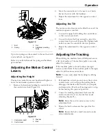
Page 29: ...ower bolt just enough to pivot the control lever fore or aft Figure 20 Tighten both bolts to secure the control in the new position 3 Repeat the adjustment for the opposite control lever Adjusting the Tracking When driving the machine forward full speed across a flat level surface if the machine pulls to one side adjust the tracking If the machine pulls to the left adjust the right motion control ...

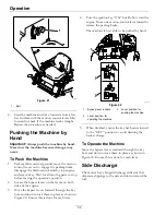
Page 30: ...f the engine 3 Move the bypass levers forward through the key hole and down to lock them in place as shown in Figure 22 Ensure this is done for each lever 4 Turn the ignition key ON but Do Not start the engine Move one motion control lever inward to release the parking brake The machine is now able to be pushed by hand g333974 Figure 22 1 Bypass lever location 3 Lever position for pushing the mach...

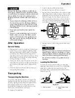
Page 31: ...ve before storing or transporting the machine Transporting Transporting the Machine Use a heavy duty trailer or truck to transport the machine Ensure that the trailer or truck has all necessary lighting and marking as required by law Thoroughly read all of the safety instructions Knowing this information could help you your family pets or bystanders avoid injury To transport the machine Lock the b...

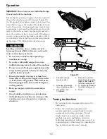
Page 32: ...angle between the ramp and the ground or between the ramp and the trailer or truck Ensure the length of ramp is at least four times 4X as long as the height of the trailer or truck bed to the ground This will ensure that ramp angle does not exceed 15 degrees on flat ground Back up ramps and drive forward down ramps Avoid sudden acceleration or deceleration while driving the machine on a ramp as th...

Page 33: ... different times So to maintain the same cutting height which is a good practice mow more often in early spring As the grass growth rate slows in mid summer mow less frequently If you cannot mow for an extended period first mow at a high cutting height then mow again two days later at a lower height setting Cutting Speed To improve cut quality use a slower ground speed Avoid Cutting Too Low If the...

Page 34: ...d to serious injury or death Unauthorized changes to the machine engine fuel or venting system may violate applicable safety standards such as ANSI OSHA and NFPA and or government regulations such as EPA and CARB WARNING Hydraulic fluid escaping under pressure can penetrate skin and cause injury Fluid accidentally injected into the skin must be surgically removed within a few hours by a doctor fam...

Page 35: ...eaner foam element more often in dusty dirty conditions Exmark engine Change the engine oil change it more often under a heavy load or in high temperatures Exmark Engine Check the spark plug Exmark engine Replace the air cleaner paper element more often in dusty dirty conditions Kohler engine Change the engine oil change it more often under a heavy load or in high temperatures Kohler Engine Check ...

Page 36: ...1500 m for a continuous period ensure that the High Altitude Kit has been installed so that the engine meets CARB EPA emission regulations The High Altitude Kit increases engine performance while preventing spark fouling hard starting and increased emissions Once you have installed the kit attach the high altitude label next to the serial decal on the machine reference Figure 1 Contact an Authoriz...

Page 37: ...debris around the air cleaner system Keep this area clean Also check for loose or damaged components Replace all bent or damaged air cleaner components Note Operating the engine with loose or damaged air cleaner components could allow unfiltered air into the engine causing premature wear and failure Note Service the air cleaner more often under extremely dusty dirty conditions Removing the Element...

Page 38: ...y result 1 Park machine on level ground move the motion control levers out to engage the parking brake disengage the blade control switch stop engine and remove key Wait for all moving parts to stop before leaving the operator s position 2 Make sure the engine is stopped level and is cool so the oil has had time to drain into the sump 3 To keep dirt grass clippings etc out of the engine clean the ...

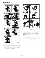
Page 39: ...hours Every 100 hours change it more often under a heavy load or in high temperatures Exmark Engine 1 Park the machine so that the drain side is slightly lower than the opposite side to ensure the oil drains completely 2 Start the engine and let it run until warm This warms the oil so it drains better 3 Disengage the blade control switch and ensure the parking brake is engaged 4 Stop the engine re...

Page 40: ...rubber gasket on the new filter g027477 Figure 36 Note Ensure the oil filter gasket touches the engine then an extra 3 4 turn is completed Note Dispose of the used oil at a recycling center 6 Slowly pour approximately 80 of the specified oil into the filler tube use oil recommended in the Checking the Engine Oil Level section 40 ...

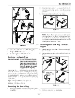
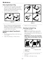
Page 41: ... plug if necessary Type Champion RN9YC or equivalent Air Gap 0 030 inch 76 mm Removing the Spark Plug 1 Disengage the PTO and ensure the parking brake is engaged 2 Stop the engine remove the key and wait for all moving parts to stop before leaving the operating position 3 Disconnect the wire from the spark plug g027478 Figure 38 Note Due to the deep recess around the spark plug blowing out the cav...

Page 42: ...engine with loose or damaged air cleaner components could allow unfiltered air into the engine causing premature wear and failure Removing the Elements 1 Park machine on level ground move the motion control levers out to engage the parking brake disengage the blade control switch stop engine and remove key Wait for all moving parts to stop before leaving the operator s position 2 Move the motion c...

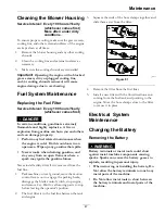
Page 43: ...or daily Important Do not overfill the crankcase with oil and run the engine engine damage may result 1 Park machine on level ground move the motion control levers out to engage the parking brake disengage the blade control switch stop engine and remove key Wait for all moving parts to stop before leaving the operator s position 2 Make sure the engine is stopped level and is cool so the oil has ha...

Page 44: ... temperatures Kohler Engine 1 Park the machine so that the drain side is slightly lower than the opposite side to ensure the oil drains completely 2 Start the engine and let it run until warm This warms the oil so it drains better 3 Move the motion control levers out to engage the parking brake disengage the blade control switch stop engine and remove key Wait for all moving parts to stop before l...

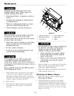
Page 45: ...ne Oil Level section 7 Start the engine and check for leaks Servicing the Spark Plug Service Interval Every 100 hours Yearly whichever comes first Every 500 hours Every 2 years whichever comes first Replace the spark plug Kohler engine Ensure that the air gap between the center and side electrodes is correct before installing the spark plug Use a spark plug wrench for removing and installing the s...

Page 46: ...leaning Installing the Spark Plug Exmark Engine 1 Install the spark plug Make sure that the air gap is set correctly 2 Tighten the spark plug to 15 ft lb 20 N m g027480 Figure 49 3 Push the wire onto the spark plug Checking the Spark Plug 1 Inspect the spark plug Note If you see light brown or gray on the insulator the engine is operating properly A black coating on the insulator usually means the...

Page 47: ...ining gasoline and stay away from an open flame or where a spark may ignite the gasoline fumes Never install a dirty filter if it is removed from the fuel line 1 Park machine on level ground move the motion control levers out to engage the parking brake disengage the blade control switch stop engine and remove key Wait for all moving parts to stop before leaving the operator s position 2 The fuel ...

Page 48: ...the parking brake disengage the blade control switch stop engine and remove key Wait for all moving parts to stop before leaving the operator s position 2 Raise the seat 3 Disconnect the negative black ground cable from the battery post Figure 52 Retain all fasteners g009783 Figure 52 1 Negative battery post 4 Positive battery post 2 Bolt washer and nut 5 Battery strap 3 Terminal boot 6 Battery WA...

Page 49: ... or corroded battery terminals or damage to the engine may occur DANGER Jump starting a weak battery that is cracked frozen has low electrolyte level or an open shorted battery cell can cause an explosion resulting in serious personal injury Do Not jump start a weak battery if these conditions exist 2 Make sure the booster is a good and fully charged lead acid battery at 12 6 volts or greater Use ...

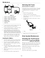
Page 50: ...previously 3 Install the negative battery cable to the negative battery terminal using the fasteners removed previously 4 Slide the red terminal boot onto the positive red battery post 5 Secure the battery with the strap Figure 52 Servicing the Fuses Service Interval As required The electrical system is protected by fuses It requires no maintenance however if a fuse blows check the component circu...

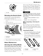
Page 51: ...sharpen the blades as necessary If a blade is damaged or worn replace it immediately with a genuine Exmark replacement blade For convenient sharpening and replacement you may want to keep extra blades on hand WARNING A worn or damaged blade can break and a piece of the blade could be thrown into the operator s or bystander s area resulting in serious personal injury or death Inspect the blade peri...

Page 52: ...es so that the opposing cutting edge is now in the same position g009681 Figure 60 1 Blade side previously measured 2 Measurement position used previously 3 Opposing side of blade being moved into measurement position 5 Measure from the tip of the blade to the flat surface here The variance should be no more than 1 8 inch 3mm g009680 Figure 61 1 Opposing blade edge in position for measuring 2 Leve...

Page 53: ...he spindle shaft Figure 62 g014975 Figure 62 1 Sail area of blade 3 Curved washer 2 Blade 4 Blade bolt Sharpening the Blades 1 Use a file to sharpen the cutting edge at both ends of the blade Figure 63 Maintain the original angle The blade retains its balance if the same amount of material is removed from both cutting edges g007276 Figure 63 1 Sharpen at original angle 2 Check the balance of the b...

Page 54: ... the blades so that they are all side to side Figure 65 and Figure 66 g009682 Figure 65 Mower Deck with 2 Blades 1 Blades side to side 3 Outside cutting edges 2 Sail area of blade 4 Measure from the tip of the blade to the flat surface here g005278 Figure 66 Mower Deck with 3 Blades 1 Blades side to side 3 Outside cutting edges 2 Sail area of blade 4 Measure from the tip of the blade to the flat s...

Page 55: ...ction Adjusting the Front to Rear Blade Slope Check the front to rear blade level any time you install the mower If the front of the mower is more than 5 16 inch 7 9 mm lower than the rear of the mower adjust the blade level using the following instructions 1 Park machine on level ground move the motion control levers out to engage the parking brake disengage the blade control switch stop engine a...

Page 56: ...e adjustment nut 7 After adjustment check the front to rear slope again Continue adjusting the nut until the front blade tip is 1 16 5 16 inch 1 6 7 9 mm lower than the rear blade tip Figure 69 and Figure 70 8 When the front to rear blade slope is correct check the side to side level of the mower again refer to Side to Side Leveling Removing the Mower Deck Service Interval As required 1 Park machi...

Page 57: ...t arm 3 Washer 2 Hairpin cotter C Remove the lift arm from the deck pin D Repeat steps B and C for the other side of the machine E Slide the mower deck rearward to remove the mower belt from the engine pulley For 54 Inch Models A At the rear of the mower deck remove the two shoulder bolts and nuts securing the deck to the pivot pan g299079 Figure 74 1 Nut 3 Shoulder bolt 2 Pivot pan 57 ...

Page 58: ...the lift arm using the washer and hairpin cotter C Repeat steps A and B for the other side of the machine For 54 Inch Models A Lift the rear of the mower deck and attach the rear deck hangers to the rear deck pins reference Figure 75 B Attach the front deck hangers to the front deck pins C Secure the deck pins with the hairpin cotters and washers removed previously D Secure the rear of the deck to...

Page 59: ...spring over the deck hook and placing tension on the idler pulley and mower belt Replacing the Discharge Deflector DANGER An uncovered discharge opening could allow the lawn mower to throw objects in the operator s or bystander s direction and result in serious injury Also contact with the blade could occur Never operate the lawn mower unless you install a mulch plate discharge deflector or grass ...

Page 60: ... switch stop engine and remove key and wait for all moving parts to stop before leaving the operating position 2 Remove the nut 3 8 inch from the rod under the mower Figure 79 g296957 Figure 79 1 Mower deck 5 Rod 2 Short standoff 6 Spring 3 Discharge deflector bracket 7 Nut 3 8 inch 4 Discharge deflector 3 Slide the rod out of the short standoff spring and discharge deflector 4 Remove the damaged ...

Page 61: ...engine move the motion control levers out to engage the parking brake wait for all moving parts to stop and remove key 2 Clean off any oil debris or grass build up on the machine and cutting deck especially under deck belt shields around the fuel tank around engine and exhaust area Important You can wash the machine with mild detergent and water Do not pressure wash the machine Avoid excessive use...

Page 62: ...o Not swallow electrolyte In the event of an accident flush with water and call a doctor immediately Federal law states that batteries should not be placed in the garbage Management and disposal practices must be within relevant federal state or local laws If a battery is being replaced or if the unit containing the battery is no longer operating and is being scrapped take the battery to a local c...

Page 63: ... 1 Move the blade control switch to disengaged 2 The motion control levers are not in the park brake position 2 Move the motion control levers outward to the parking brake position 3 The operator is not seated 3 Sit on the seat 4 Battery does not have a full charge 4 Charge the battery See Check Battery Charge and Recommended Jump Starting Procedure sections in Maintenance 5 The electrical connect...

Page 64: ...y or blade pulley 2 Tighten the appropriate pulley 3 Engine pulley is damaged 3 Contact an Authorized Service Dealer 4 Cutting blade s is are bent or unbalanced 4 Install new cutting blade s 5 Blade is loose 5 Tighten the blade mounting bolt and inspect the blade spring disc washer for damage See Servicing the Cutting Blades section Abnormal vibration 6 Blade spindle is bent 6 Contact an Authorize...

Page 65: ...Schematics Schematics Electrical Logic Schematic g330623 65 ...

Page 66: ...estaurants grocery stores hotels schools and hospitals and on a wide variety of products Additionally some online and mail order retailers provide Prop 65 warnings on their websites or in catalogs How do the California warnings compare to federal limits Prop 65 standards are often more stringent than federal and international standards There are various substances that require a Prop 65 warning at...

Page 67: ...Notes 67 ...

Page 68: ...Notes 68 ...

Page 69: ...Service Record Date Description of Work Done Service Done By 69 ...

Page 70: ...70 ...

Page 71: ...he slope indicator to determine the degree of slope of hills before operating Do Not operate this machine on a slope greater than 15 degrees Fold along the appropriate line to match the recommended slope 2 Align this edge with a vertical surface a tree building fence pole etc 3 Example of how to compare slope with folded edge 71 ...

Page 72: ...TOM RIDE SEAT SUSPENSION SYSTEM DUAL TAIL WHEEL FLOOR PAN EXTENDER HITCH KIT LIGHT KIT MICRO MULCH SYSTEM ROLL OVER PROTECTION SYSTEM ROPS SNOW BLADE SNOWBLOWER SUN SHADE TRASH CONTAINER ULTRA VAC COLLECTION SYSTEM ULTRA VAC QUICK DISPOSAL SYSTEM WEATHER CAB Some accessories and options not available for some models Place Model No and Serial No Label Here Included in the Literature Pack or Fill in...

Reviews: