Operation
g014657
Figure 10
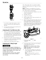
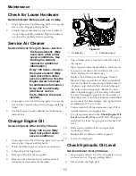
To turn left or right, release pressure on the
motion control lever toward the desired turn
direction.
3.
To stop, position both motion control levers in
the neutral operate position.
Adjusting the Front Reference Bar
1.
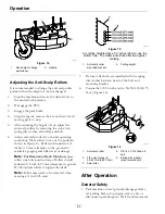
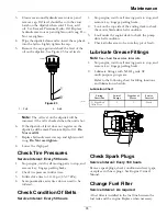
Insert a 7/32 inch allen wrench through the hole
on one side of the control tower panel. Place
a 9/16 inch wrench on the corresponding nut
located underneath the control tower. Loosen the
bolt and repeat for the opposite side of the front
reference bar (see Figure 8).
2.
Rotate the bar forward or rearward, limiting the
forward travel of the control levers until desired
maximum forward speed is achieved.
3.
Tighten bolts to lock reference bar in place.
Adjusting the Cutting Height
WARNING
When the two front support rod hairpins are
removed from the mower deck, the weight of the
tractor section may cause the front frame of the
machine to rise suddenly. If the machine rises
suddenly, injury may occur.
Securely hold down the front of the machine
when raising the mower deck for hairpin
repositioning.
The cutting height of the mower deck is adjusted
from 1 to 5 inches (25 mm to 127 mm) in 1/2 inch
increments.
Note:
Mowing for extended periods of time at 1
inch height of cut may result in reduced deck belt life
due to increased belt operating angle.
1.
Stop the machine and move the drive levers to the
neutral locked position.
2.
Disengage the PTO.
3.
Engage the park brake.
4.
Stop the engine, remove the key and wait for all
moving parts to stop.
5.
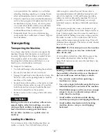
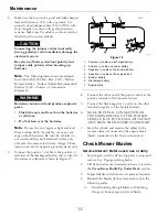
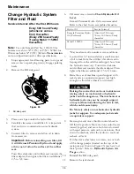
Lift the cutting deck using the handle as shown in
Figure 11(handle position varies with deck size)
to the highest position possible. Engage deck
height change assist lever by rotating forward until
contact with the deck support rod (see Figure 11).
While the lever is manually engaged, lower the
deck to rest on the lever.
g303934
Figure 11
1.
Deck height change
assist lever
2.
Handle
6.
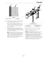
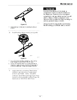
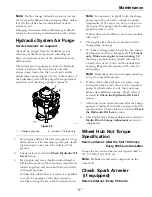
Install hairpin clips in the holes for the desired
cutting height. See Figure 12.
Important:
To maintain correct cutting
height and rake, check the following for
proper adjustment.
A.
The front and rear hairpins are in the same
holes with the proper spacers under the hair
pins. See Figure 12.
Note:
All deck pins have a groove at
the 3 inch (76 mm) cut height for ease of
identification.
22


