background image

Maintenance

Mower Deck Drive Belt
Tension

Self-tensioning - No adjustment necessary.

Park Brake Adjustment

If the parking brake does not hold securely, an
adjustment is required.

1.

Park the machine on a level surface.

2.

Shut off engine and wait for all moving parts to
stop.

3.

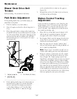
When the park brake is released, the brake bars
should lift off the tires and the hand lever should
travel forward. When the brake is disengaged, the
gap between the brake snubber teeth and drive
tire should measure 1/2–5/8 inch (13–16 mm)
(see Figure 28).

g271524

Figure 28

1.

Hairpin and washer

3.

1/2–5/8 inch (13–16 mm)

2.

4.69–4.81 inch
(11.9–12.2 cm)

4.

If the parking brake does not hold securely an
adjustment is required. To adjust the brake,
remove and retain the hairpin and washer
on the brake linkage rod. Turn the brake
linkage rod clockwise to decrease the gap

and counterclockwise to increase the gap (see
Figure 28).

5.

Reinstall the rod into the brake lever and secure
with the washer and hairpin.

Motion Control Tracking
Adjustment

Located in the front inside the tower. Rotating the
pump linkage with a 9/16 inch wrench allows fine
tuning adjustments so that the machine does not
move in neutral. Any adjustments should be made
for neutral positioning only.

1.

Raise the rear of machine up and support with
jack stands (or equivalent support) just high
enough to allow drive wheels to turn freely.

2.

Start engine. Brake must be engaged and motion
control levers out to start engine. Run engine at
full throttle and release brake.

3.

Run the unit at least 5 minutes with the drive
levers at full forward speed to bring hydraulic oil
up to operating temperature.

Note:

The motion control lever needs to be in

neutral while making any necessary adjustments.

4.

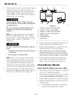
Bring the motion control levers into the neutral
position. Access the links from the front of the
tower (Figure 29). Adjust pump control rod
lengths by loosening the bottom nuts on each and
rotating the turn buckle until the wheels slightly
creep in reverse (Figure 29). Pumps have a return
to neutral arms and will return to neutral when
the control levers are released. If the levers do not
fold out, adjust the links until the lever folds out
in the middle of the neutral lock notch. Move the
levers to the full forward and reverse. If the levers
fold out, tighten the jam nuts on the links.

40


Summary of Contents for STARIS E Series

Page 1: ...STARIS E SERIES For Serial Nos 406 294 345 Higher Part No 4504 758 Rev A ...

Page 2: ...e is equipped with a spark arrester as defined in Section 4442 maintained in effective working order or the engine is constructed equipped and maintained for the prevention of fire To acquire a spark arrester for your unit see your Engine Service Dealer For all models that do not have Exmark engines please refer to the engine manufacturer s information included with the machine For models with Exm...

Page 3: ... materials and Operator s manuals If additional information is needed or should you require trained mechanic service contact your authorized Exmark equipment dealer or distributor All Exmark equipment dealers and distributors are kept informed of the latest methods of servicing and are equipped to provide prompt and efficient service in the field or at their service stations They carry ample stock...

Page 4: ...34 Check Tire Pressures 35 Check Condition Of Belts 35 Lubricate Grease Fittings 35 Check Spark Plugs 35 Change Hydraulic System Filter and Fluid 36 Wheel Hub Nut Torque Specification 37 Check Spark Arrester if equipped 37 Thread Locking Adhesives 38 Mobil HTS Grease Or Food Grade Anti seize 38 Copper Based Anti seize 38 Dielectric Grease 38 Adjustments 39 Deck Leveling 39 Pump Drive Belt Tension ...

Page 5: ...bjects Exmark designed and tested this lawn mower to offer reasonably safe service however failure to comply with safety instructions may result in injury or death Read understand and follow all instructions and warnings in the Operator s Manual and other training material on the machine engine and attachments All operators and mechanics should be trained If the operator s or mechanic s can not re...

Page 6: ...c Safety signs may be affixed by peeling off the backing to expose the adhesive surface Apply only to a clean dry surface Smooth to remove any air bubbles Familiarize yourself with the following safety signs and instruction labels They are critical to the safe operation of your Exmark commercial mower decal98 1977 98 1977 1 Entanglement hazard belt stay away from moving parts decal106 5517 106 551...

Page 7: ... Warning stay away from moving parts keep all guards in place decal126 2056 126 2056 1 Wheel lug nut torque 95 ft lb 129 N m 4x 2 Wheel hub nut torque 125 ft lb 169 N m 3 Read and understand the Operator s manual before performing any maintenance check torque after first 100 hours then every 500 hours thereafter decal133 8062 133 8062 decal135 2267 135 2267 Drive Pump Belt Routing decal135 2562 13...

Page 8: ... pressure decal135 3004 135 3004 decal135 5210 135 5210 1 Thrown objects hazard keep bystanders away 2 Thrown objects hazard mower do not operate without the deflector discharge cover or grass collection system in place 3 Cutting dismemberment of hand or foot stay away from moving parts keep all guards and shields in place decal135 6844 135 6844 1 Read the Operator s manual 2 Only use Exmark 10W 5...

Page 9: ...y Keep deflector in place 2 Warning Stay away from moving parts keep all guards in place Stop engine and remove key before adjusting servicing or cleaning 5 Cutting dismemberment hazard Mow across slopes not up and down Do Not mow wet slopes use extreme caution when operating on slopes 3 Warning Disengage PTO move drive levers out to neutral lock position engage parking brake and stop engine befor...

Page 10: ...ecal135 6773 135 6773 1 Forward 5 Choke off 9 Engine off 2 Neutral 6 Throttle fast 10 Engine on 3 Reverse 7 Continuous variable setting 11 Engine start 4 Choke on 8 Throttle slow 12 Optional light accessory 10 ...

Page 11: ...ol panel Note Because the PTO must be disengaged to start the engine the LCD indicator will illuminate at this time PTO must be disengaged and motion control levers in neutral to start engine It is not necessary for the operator to be on the platform to start the engine Mower blades will stop if both motion control levers are moved or released into the neutral position Engine will stop if the moti...

Page 12: ...ounted on engine shaft Blades driven by one belt w self tensioning idlers Deck Full floating deck is attached to support frame removable for service Deck design allows for bagging mulching or side discharge Deck Depth 5 0 inches 12 7 cm Cutting Height Adjustment Adjusts from 1 inch 2 5 cm to 5 inches 12 7 cm in 1 2 inch 12 7 mm increments Mulching Kit Optional Bagger Optional Dimensions Overall Wi...

Page 13: ...s 30 35 ft lb 41 47 N m Wheel Lug Nuts 85 105 ft lb 115 142 N m Wheel Hub Nuts 115 135 ft lb 156 183 N m Wheel Motor Mounting Bolts 30 35 ft lb 41 47 N m Product Overview g260634 Figure 3 1 Height of cut pins 3 Controls 2 Park brake lever 4 Motion controls 13 ...

Page 14: ...eutral position the neutral LCD indicator will disappear and the Operator Presence indicator will appear Choke Control Located on the LH side of the control console black lever see Figure 5 The choke is used to aid in starting a cold engine Moving the choke lever forward will put the choke in the ON position and moving the choke lever to the rear to the detent will put the choke in the OFF positio...

Page 15: ...console in the message display see Figure 7 The hour meter records the number of hours that the engine has run g275343 Figure 7 1 LCD Indicators 2 Low voltage indicator light 3 Hour Voltage display The hour meter is recording when the decimal point is flashing in Hour Voltage display Hours are displayed when the key is off or when the machine is running Note If the ignition key is turned to the ON...

Page 16: ...in excess of 85 dBA at the operator s ear and can cause hearing loss through extended periods of exposure Wear hearing protection when operating this machine Check that the operator presence controls safety switches and shields are attached and functioning properly Do Not operate unless they are functioning properly Do Not operate the mower when people especially children or pets are in the area S...

Page 17: ...an ignite gasoline vapors A fire or explosion from gasoline can burn you and others and cause property damage Always place gasoline containers on the ground away from your vehicle before filling Do Not fill gasoline containers inside a vehicle or on a truck or trailer bed because interior carpets or plastic truck bed liners may insulate the container and slow the loss of any static charge When pra...

Page 18: ...cks and other hidden hazards Use care when approaching blind corners shrubs trees tall grass or other objects that may hide obstacles or obscure vision Uneven terrain could overturn the machine or cause the operator to lose their balance or footing Be sure all drives are in neutral and parking brake is engaged before starting engine Start the engine carefully according to instructions with feet we...

Page 19: ...ra caution Before using the machine on a slope the operator must Review and understand the slope instructions in the manual and on the machine Evaluate the site conditions of the day to determine if the slope is safe for machine operation Use common sense and good judgment when performing this evaluation Changes in the terrain such as moisture can quickly affect the operation of the machine on a s...

Page 20: ...kit in place and working properly The PTO switch engages the cutting blades Be sure all persons are clear of mower deck and discharge area before engaging the PTO 1 Set throttle to MIDWAY position 2 Release the parking brake 3 Move the motion control levers to the center operate position 4 Pull the PTO switch outward to engage the blades 5 Place the throttle in the FAST position to begin mowing Di...

Page 21: ...control bar 3 Front of machine 7 Forward 4 Reverse 8 Front reference bar adjustment hole Driving Forward 1 Make sure the motion control levers are in the neutral position 2 Release the parking brake 3 To move forward in a straight line move both levers forward with equal pressure g014656 Figure 9 To turn left or right pull the motion control lever back toward neutral in the desired turn direction ...

Page 22: ...rpin repositioning The cutting height of the mower deck is adjusted from 1 to 5 inches 25 mm to 127 mm in 1 2 inch increments Note Mowing for extended periods of time at 1 inch height of cut may result in reduced deck belt life due to increased belt operating angle 1 Stop the machine and move the drive levers to the neutral locked position 2 Disengage the PTO 3 Engage the park brake 4 Stop the eng...

Page 23: ...stment in the length of the rear deck support assemblies may be necessary If one side is longer than 6 38 inches 162 mm than the opposite side must be shorter by the same amount g303985 Figure 13 Left Hand Side Shown 1 3 8 inch 9 5 mm 3 6 38 inches 162 mm 2 1 4 inch 6 4 mm 4 Deck support rod 7 Repeat steps 5 and 6 for the opposite side 8 Lift deck to unlatch Figure 14 Note Deck height change assis...

Page 24: ...mage Note For Maximum Deck Flotation place rollers one hole position lower Rollers should maintain 1 4 inch 6 35 mm clearance to ground Do Not adjust rollers to support the deck Note Roller may need to be removed when mowing at 1 inch 25 mm g224809 Figure 15 For cutting heights above 3 5 inches 38 mm use the bottom hole The rollers will still be effective against scalping 1 Anti scalp roller mount...

Page 25: ...ry Do not drive machine on a public street or roadway Loading the Machine Use extreme caution when loading machines on trailers or trucks One full width ramp that is wide enough to extend beyond the rear tires is recommended instead of individual ramps for each side of the machine A full width ramp provides a surface to walk on behind the machine If it is not possible to use one full width ramp us...

Page 26: ...th the manufacturer s recommended parts when necessary WARNING Removal or modification of original equipment parts and or accessories may alter the warranty controllability and safety of the machine Unauthorized modifications to the original equipment or failure to use original Exmark parts could lead to serious injury or death Unauthorized changes to the machine engine fuel or venting system may ...

Page 27: ... wheel hub torque specification Check the wheel lug nuts After the first 250 hours Change the hydraulic filter and fluid Before each use or daily Check the engine oil level Check the mower blades Check the safety interlock system Check for loose hardware Clean the grass and debris build up from the machine and cutting deck Clean the engine and exhaust system area Clean the grass build up from unde...

Page 28: ...271490 Figure 18 1 Rear guard 2 Slot Installing the Rear Guard Service Interval As required To reinstall the rear guard insert the three tabs into the slots in the bottom of the frame see Figure 18 Push the guard forward and snap over the brake shaft Check Engine Oil Level Service Interval Before each use or daily 1 Stop engine and wait for all moving parts to stop Make sure unit is on a level sur...

Page 29: ...the ignition is in the ON position there is potential for sparks and engagement of components Sparks could cause an explosion or moving parts could accidentally engage causing personal injury Be sure ignition switch is in the OFF position before charging the battery Check the voltage of the battery with a digital voltmeter or with the message display When the ignition is set to the accessory mode ...

Page 30: ...ystems only 3 Connect the positive cable to the positive terminal of the discharged battery that is wired to the starter or solenoid as shown in Figure 19 g012785 Figure 19 1 Positive cable on discharged battery 2 Positive cable on booster battery 3 Negative cable on the booster battery 4 Negative cable on the engine block 5 Booster battery 6 Discharged battery 7 Engine block 4 Connect the other e...

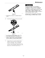
Page 31: ... lubricant to threads of blade bolt as needed to prevent seizing Copper based anti seize preferable Grease acceptable substitute Install blade bolt finger tight Place wrench on the top spindle nut then torque the blade bolts to 50 60 ft lb 68 81 N m WARNING Incorrect installation of the blade or components used to retain the blade can be dangerous Failure to use all original components and assembl...

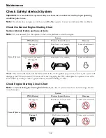
Page 32: ... should crank Up position but blades disengaged Both levers out neutral Starter should crank State of System Note The starter will crank with the PTO switch in the ON pulled up position however the system will disengage the PTO and a reset PTO error will occur Engaging the PTO will require the operator to reset the PTO switch by turning it OFF pushed down and then turning it ON Check Engine Starti...

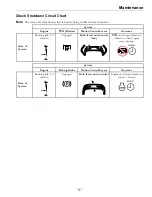
Page 33: ...tion Control Levers Outcome Running idle 1 3 throttle Engaged Both levers out neutral lock PTO must begin shutdown within 1 second engine stays running State of System System Engine Parking Brake Motion Control Levers Outcome Running idle 1 3 throttle Engaged Both levers not in neutral Engine must begin shutdown within 1 second State of System 33 ...

Page 34: ...ain the rear guard 5 Remove and retain the knob washer and air deflector located under the machine g271831 Figure 22 1 Air deflector 2 Knob and washer 6 The oil drain valve is located on the left side of the engine Place the pan under the machine to catch the oil Loosen the oil drain valve and allow the oil to drain Tighten the oil drain valve 7 Replace the oil filter per the Engine Owner s Manual...

Page 35: ...late drive tires to 12 14 psi 83 97 kPa 4 Semi pneumatic caster tires do not need to be inflated Check Condition Of Belts Service Interval Every 50 hours 1 Stop engine wait for all moving parts to stop and remove key Engage parking brake 2 Look on the top side of the cutting deck to check the mower blade drive belt condition 3 Look under the engine deck to check the pump drive belt condition 4 Che...

Page 36: ...hours Every 500 hours Yearly thereafter Mobil 1 15W50 After first 250 hours Every 250 hours Yearly thereafter May need more often under severe conditions 7 Loosen filter 1 2 turn and allow a small amount of oil to leak from the oil filter this allows air to be purged from the oil filter and supply hose from the hydraulic reservoir Turn filter clockwise until rubber seal contacts the filter adapter...

Page 37: ... the forward position Note It is necessary to lightly touch the charge pump cap with your hand to check the pump temperature If the cap is too hot to touch turn off engine The pumps may be damaged if the pump becomes too hot If either drive wheel still does not rotate continue with step 4 4 Thoroughly clean the area around each of the charge pump housings 5 To prime charge pump loosen two hex sock...

Page 38: ... necessary Reinstall arrester on exhaust outlet Thread Locking Adhesives Thread locking adhesives such as Loctite 242 or Fel Pro Pro Lock Nut Type are used on the following fasteners Pump sheave setscrews Sheave retaining bolt in end of engine crankshaft Mobil HTS Grease Or Food Grade Anti seize Mobil HTS grease or food grade anti seize is used in the following locations Between splines of the cut...

Page 39: ...the 3 inch 7 6 cm position 5 Raise the discharge deflector 6 Carefully rotate the blades front to rear Measure from the tip of the front blade to the level surface Figure 26 The blades should measure 3 inches 7 6 cm 1 8 inch 3 cm Note In most conditions the back tips should be adjusted 3 16 1 4 inch 4 6 6 4 mm higher than the front g014790 Figure 26 1 3 1 4 inches 8 3 cm 4 3 inches 7 6 cm 2 Back b...

Page 40: ...e pump linkage with a 9 16 inch wrench allows fine tuning adjustments so that the machine does not move in neutral Any adjustments should be made for neutral positioning only 1 Raise the rear of machine up and support with jack stands or equivalent support just high enough to allow drive wheels to turn freely 2 Start engine Brake must be engaged and motion control levers out to start engine Run en...

Page 41: ...tally with the left motion control lever g012878 Figure 30 1 LH Motion control lever 2 RH Motion control lever 3 RH Motion control lever in PTO disengage position 4 Check the horizontal alignment here 4 To adjust the right motion control lever horizontally the cam needs to be adjusted 5 Release the cushion from the rear of the machine 6 Loosen the nut holding the cam see Figure 31 g267325 Figure 3...

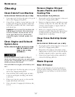
Page 42: ...ding and exhaust system area 3 Wipe up any excessive grease or oil around the engine and exhaust system area 4 Clean oil coolers if equipped of all debris dirt and oil Remove Engine Shroud Access Panels and Clean Cooling Fins Service Interval Every 80 hours 1 Stop engine wait for all moving parts to stop and remove key Engage parking brake 2 Remove cooling shroud access panels from engine and clea...

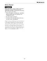
Page 43: ...o Not swallow electrolyte In the event of an accident flush with water and call a doctor immediately Federal law states that batteries should not be placed in the garbage Management and disposal practices must be within relevant federal state or local laws If a battery is being replaced or if the unit containing the battery is no longer operating and is being scrapped take the battery to a local c...

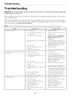
Page 44: ...ct an Authorized Service Dealer 1 Fuel tank is empty 1 Fill the fuel tank 2 Fuel shutoff valve is closed 2 Open the fuel shutoff valve 3 The throttle and choke are not in the correct position 3 Be sure the throttle control is midway between the SLOW and FAST positions and the choke is in the ON position for a cold engine or the OFF position for a warm engine 4 Dirt in fuel filter 4 Replace the fue...

Page 45: ...e pressure in drive tires not correct 5 Adjust tire pressure in the drive tires 6 Blade spindle bent 6 Contact an Authorized Service Dealer Uneven cutting height 7 Tips of adjacent blades are at an uneven cutting height Blades tips should be even within 3 16 inch which is approximately one blade thickness 7 Replace blades spindles and or check for damage to mower deck 1 Cutting blade s is are bent...

Page 46: ...cessary 2 Low voltage supply at the clutch 2 Check coil resistance battery charge charging system and wiring connections and replace if necessary 3 Damaged coil 3 Replace clutch 4 Inadequate current supply 4 Repair or replace clutch lead wire or electrical system Clean connector contacts Clutch will not engage 5 Rotor armature airgap is too large 5 Remove shim or replace clutch 46 ...

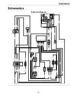
Page 47: ... BLUE RED BLUE RED RED GREEN YELLOW WHITE GND ACC Y PWR ACC Y SIGNL CAP01 ACC Y P7012 A B C DIS7001 HOUR METER P7011 1 PTO OUT 2 GND 3 START 4 NEUTRAL 5 OPC 6 UNUSED 7 GND S D 8 BRAKE 9 PTO IN 10 KEY S 11 B 12 UNUSED S IGNITION SWITCH SW7001 RUN START B OFF I A P7008 D P7008 C A B VIOLET RED BLACK P7005 A B C D E F G H BLACK BLACK YELLOW WHITE YELLOW BLACK SP7008 D7001 FUEL FLYBACK DIODE P7003 B P...

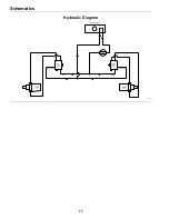
Page 48: ...Schematics Hydraulic Diagram g270319 48 ...

Page 49: ...estaurants grocery stores hotels schools and hospitals and on a wide variety of products Additionally some online and mail order retailers provide Prop 65 warnings on their websites or in catalogs How do the California warnings compare to federal limits Prop 65 standards are often more stringent than federal and international standards There are various substances that require a Prop 65 warning at...

Page 50: ...Service Record Date Description of Work Done Service Done By 50 ...

Page 51: ...51 ...

Page 52: ...STOM RIDE SEAT SUSPENSION SYSTEM DUAL TAIL WHEEL FLOOR PAN EXTENDER HITCH KIT LIGHT KIT MICRO MULCH SYSTEM ROLL OVER PROTECTION SYSTEM ROPS SNOW BLADE SNOWBLOWER SUN SHADE TRASH CONTAINER ULTRA VAC COLLECTION SYSTEM ULTRA VAC QUICK DISPOSAL SYSTEM WEATHER CAB Some accessories and options not available for some models Place Model No and Serial No Label Here Included in the Literature Pack or Fill i...

Reviews: