background image

Service Record

Date:

Description of Work Done:

Service Done By:

41

Summary of Contents for TURF TRACER TT23KAEP

Page 1: ...TURF TRACER TT23KAEP MODEL ONLY For Serial Nos 790 000 Higher Part No 4500 382 Rev A ...

Page 2: ...pplied for information regarding The U S Environmental Protection Agency EPA and the California Emission Control Regulation of emission systems maintenance and warranty Keep this engine Owner s Manual with your unit Should this engine Owner s Manual become damaged or illegible replace immediately Replacements may be ordered through the engine manufacturer Exmark reserves the right to make changes ...

Page 3: ...tributor All Exmark equipment dealers and distributors are kept informed of the latest methods of servicing and are equipped to provide prompt and efficient service in the field or at their service stations They carry ample stock of service parts or can secure them promptly for you from the factory All Exmark parts are thoroughly tested and inspected before leaving the factory however attention is...

Page 4: ...Belts 25 Lubricate Grease Fittings 25 Lubricate Caster Wheel Hubs 26 Remove Engine Shrouds and Clean Cooling Fins 26 Check Spark Plugs 26 Change Hydraulic System Filter 27 Wheel Hub Slotted Nut Torque Specification 28 Thread Locking Adhesives 28 Mobil HTS Grease Or Food Grade Anti seize 29 Copper Based Anti seize 29 Dielectric Grease 29 Adjustments 29 Deck Leveling 29 Pump Drive Belt Tension 29 De...

Page 5: ... mechanic s can not read English it is the owner s responsibility to explain this material to them Become familiar with the safe operation of the equipment operator controls and safety signs All operators and mechanics should be trained The owner is responsible for training the users Never let children or untrained people operate or service the equipment Local regulations may restrict the age of t...

Page 6: ...during fueling static electricity can be released causing a spark which can ignite gasoline vapors A fire or explosion from gasoline can burn you and others and cause property damage Always place gasoline containers on the ground away from your vehicle before filling Do Not fill gasoline containers inside a vehicle or on a truck or trailer bed because interior carpets or plastic truck bed liners m...

Page 7: ...ning or working on the mower After striking a foreign object or abnormal vibration occurs inspect the mower for damage and make repairs before restarting and operating the mower Before clearing blockages Whenever you leave the mower Stop engine wait for all moving parts to stop and engage parking brake Before refueling Before dumping the grass catcher Before making height adjustments WARNING Hands...

Page 8: ...t set parking brake stop engine and remove key or disconnect spark plug wire Wait for all movement to stop before adjusting cleaning or repairing Keep engine and engine area free from accumulation of grass leaves excessive grease or oil and other debris which can accumulate in these areas These materials can become combustible and may result in a fire Let engine cool before storing and do not stor...

Page 9: ...id hoses and lines are in good condition and all hydraulic connections and fittings are tight before applying pressure to hydraulic system Keep body and hands away from pinhole leaks or nozzles that eject high pressure hydraulic fluid Use cardboard or paper not your hands to find hydraulic leaks Safely relieve all pressure in the hydraulic system by placing the motion control levers in neutral and...

Page 10: ... been installed make sure current safety signs are visible New safety signs may be obtained from your authorized Exmark equipment dealer or distributor or from Exmark Mfg Co Inc Safety signs may be affixed by peeling off the backing to expose the adhesive surface Apply only to a clean dry surface Smooth to remove any air bubbles Familiarize yourself with the following safety signs and instruction ...

Page 11: ...Safety 103 2432 103 4935 116 0404 11 ...

Page 12: ...ngine to stop if speed control lever is not in neutral and or PTO is engaged Park brake must be engaged to move speed control out of neutral or engine will kill Operator Controls Steering Control Fingertip drive control levers provide independent speed control braking and neutral to each drive wheel for moving forward or reverse stopping and power turning Transmission Two Hydro Gear variable displ...

Page 13: ...lows for bagging mulching or side discharge Deck Depth 52 inch Deck 5 5 inches 14 0 cm 60 inch Deck 5 5 inches 14 0 cm Cutting Height Adjustment Adjusts from 1 1 2 inches 3 8 cm to 4 1 2 inches 11 4 cm in 1 2 inch 1 3 cm increments Mulching Kit Optional Bagger Optional Dimensions Overall Width 52 inch Deck 60 inch Deck Deflector Up 53 4 inches 135 6 cm 61 4 inches 156 0 cm Deflector Down 64 8 inch...

Page 14: ...er Hex Capscrew See Figure 8 50 55 ft lb 68 75 N m Type 3 Hardware Anti Scalp Roller Flanged Nyloc Nut See Figure 8 30 35 ft lb 41 47 N m Type 4 Hardware Anti Scalp Roller Whizlock Nut See Figure 8 30 35 ft lb 41 47 N m Type 4 Hardware Anti Scalp Roller Nyloc Nut See Figure 8 30 35 ft lb 41 47 N m Engine Mounting Bolts 15 20 ft lb 20 27 N m Wheel Lug Nuts 90 95 ft lb 122 129 N m Wheel Hub Slotted ...

Page 15: ...ht hand lever causes the left hand and or right hand drive wheel respectively to slow down stop or reverse depending on how far each drive lever is squeezed Squeezing the drive levers beyond the neutral position causes the drive wheels to engage in the reverse direction regardless of the position of the neutral lock latches and the speed control lever Neutral Lock Latches Located directly above th...

Page 16: ...machine will not be used for a few days Rotate valve 1 4 turn clockwise to shut fuel off Rotate valve 1 4 turn counterclockwise to turn fuel on Drive Wheel Release Valves Located on the left rear corner of the hydrostatic pumps Drive wheel release valves are used to release the hydrostatic drive system to allow the machine to be moved by hand without the engine running With a 5 8 wrench turn both ...

Page 17: ...R An uncovered discharge opening will allow objects to be thrown in an operator s or bystander s direction Also contact with the blade could occur Thrown objects or blade contact can cause serious injury or death Never operate the mower with the discharge deflector raised removed or altered unless there is a grass collection system or mulch kit in place and working properly The PTO switch engages ...

Page 18: ...ght and the left hand drive lever to turn left To make a zero turn squeeze either the left hand or the right hand drive lever back into the reverse position while the opposite drive lever is in a forward position at an equal but opposite speed Note For smooth operation of this machine avoid quick jerky movements of the drive levers Move the drive levers smoothly and deliberately To stop squeeze dr...

Page 19: ...own Adjusting the Anti Scalp Rollers It is recommended to change the anti scalp roller position when the height of cut has changed 1 Stop the machine and move the drive levers to the neutral locked position 2 Disengage the PTO 3 Engage the park brake 4 Stop the engine remove the key and wait for all moving parts to stop 5 After adjusting the height of cut adjust the anti scalp rollers by removing ...

Page 20: ...nyloc nut and heavy flat washer Torque to 30 35 ft lb 41 47 N m 11 Type 3 3 8 flanged nyloc nut without washer Torque to 30 35 ft lb 41 47 N m 12 Type 4 3 8 nyloc nut Torque to 30 35 ft lb 41 47 N m Transporting Transporting a Unit WARNING Loading the mower onto a trailer without strong enough or properly supported ramps could be dangerous The ramps could collapse causing the unit to fall which co...

Page 21: ...ter the first 100 hours Check the wheel hub slotted nut torque specifications After the first 250 hours Change the hydraulic filter Before each use or daily Check the engine oil level Check the mower blades Check the safety interlock system Check for loose hardware Clean the grass build up from under the deck Every 40 hours Check the hydraulic oil level Check the tire pressures Check the condition...

Page 22: ...lead compounds chemicals known to the State of California to cause cancer and reproductive harm Wash hands after handling Allowing batteries to stand for an extended period of time without recharging them will result in reduced performance and service life To preserve optimum battery performance and life recharge batteries in storage when the open circuit voltage drops to 12 4 volts Note To preven...

Page 23: ...sed to retain the blade can be dangerous Failure to use all original components and assembled as shown could allow a blade or blade component to be thrown out from under the deck resulting in serious personal injury or death Always install the original Exmark blades blade bushings and blade bolts as shown Check Safety Interlock System Service Interval Before each use or daily 1 Check starting circ...

Page 24: ...ne Oil Service Interval After the first 5 hours Every 100 hours May need more often under severe conditions 1 Stop engine wait for all moving parts to stop and remove key Engage parking brake 2 Drain oil while engine is warm from operation 3 The oil drain hose is located on right hand side of engine Place pan under machine to catch oil Remove plug from end of drain hose Allow oil to drain and repl...

Page 25: ...oving parts to stop and remove key Engage parking brake 2 Remove the three mower deck belt shields to check mower primary and secondary belt condition 3 Look under engine deck to check the pump drive belt condition 4 Check all idler arms to be sure they pivot freely Lubricate Grease Fittings Note See chart for service intervals 1 Stop engine wait for all moving parts to stop and remove key Engage ...

Page 26: ...I grade 1 multi purpose grease 11 Insert the second bearing and new seal into the wheel 12 Apply a thread locking adhesive to the 2nd spacer nut and thread onto the axle with the wrench flats facing outward 13 Torque the nut to 75 80 in lb 8 9 N m loosen then re torque to 20 25 in lb 2 3 N m Make sure axle does not extend beyond either nut 14 Reinstall the seal guards over the wheel hub and insert...

Page 27: ...en filter 1 2 turn and allow a small amount of oil to leak from the oil filter this allows air to be purged from the oil filter and supply hose from the hydraulic reservoir Turn filter clockwise until rubber seal contacts the filter adapter Then tighten the filter an additional 2 3 to 3 4 turn 6 Raise the rear of machine up and support with jack stands or equivalent support just high enough to all...

Page 28: ...draulic reservoir can be pressurized up to 5 psi to speed this process 6 If either drive wheel still does not rotate stop and repeat steps 4 and 5 above for the respective pump If wheels rotate slowly the system may prime after additional running Check oil level as stated in Check the Engine Oil Level section 7 Allow unit to run several minutes after the charge pumps are primed with drive system i...

Page 29: ...type electrical connections to prevent corrosion and loss of contact Adjustments Note Disengage PTO shut off engine wait for all moving parts to stop engage parking brake and remove key before servicing cleaning or making any adjustments to the unit Deck Leveling See Adjusting the Cutting Height section in Operation Pump Drive Belt Tension Self tensioning No adjustment necessary Deck Belt Tension ...

Page 30: ...ol linkages need to be adjusted If wheels stop then go to step 7 4 Loosen the nut against the neutral control linkage yoke as shown in Figure 14 5 Adjust the neutral control linkage until the respective drive wheel stops when the lever is pulled against the neutral spring neutral position Turn the adjusting bolt approximately 1 4 turn clockwise if the wheel is turning in reverse or turn the bolt a...

Page 31: ...he spring that keeps tension on the knob should normally not need adjustment However if adjustment is needed adjust to where length of spring is about 1 inch 2 5 cm between washers Adjust spring length by turning nut at front of spring Drive Lever Linkage Adjustment 1 With rear of machine still on jack stands and engine running at full throttle move the speed control lever to the midway position M...

Page 32: ...l Before each use or daily 1 Stop engine wait for all moving parts to stop and remove key Engage parking brake 2 Raise deck to the transport maximum cutting height position Lift the front of unit and support unit using jack stands or equivalent support CAUTION Raising the mower deck for service or maintenance relying solely on mechanical or hydraulic jacks could be dangerous The mechanical or hydr...

Page 33: ...d clothing when handling electrolyte Do Not swallow electrolyte Federal law states that batteries should not be placed in the garbage Management and disposal practices must be within relevant federal state or local laws If a battery is being replaced or if the unit containing the battery is no longer operating and is being scrapped take the battery to a local certified recycling center If no local...

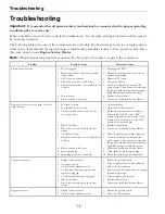
Page 34: ...shutoff valve 3 The throttle and choke are not in the correct position 3 Be sure the throttle control is midway between the SLOW and FAST positions and the choke is in the ON position for a cold engine or the OFF position for a warm engine 4 Dirt in fuel filter 4 Replace the fuel filter 5 Dirt water or stale fuel is in the fuel system 5 Contact an Authorized Service Dealer 6 Air cleaner is dirty 6...

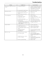
Page 35: ...ervice Dealer Uneven cutting height 7 Tips of adjacent blades are at an uneven cutting height Blades tips should be even within 3 16 inch which is approximately one blade thickness 7 Replace blades spindles and or check for damage to mower deck 1 Cutting blade s is are bent or unbalanced 1 Install new cutting blade s 2 Blade mounting bolt is loose 2 Tighten the blade mounting bolt 3 Engine mountin...

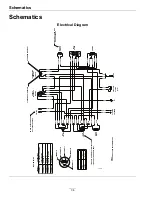
Page 36: ...RANGE ORANGE WHITE BLACK WHITE BLACK LT BLUE ORANGE ORANGE BROWN BROWN GREY YELLOW BLACK ORANGE DK BLUE BLACK WHITE BLACK WHITE BLACK WHITE BROWN BROWN WHITE BLACK BLACK BLACK ORANGE ORANGE YELLOW YELLOW YELLOW YELLOW BLACK YELLOW LT BLUE RED GREY BLACK BLACK BLACK BLACK BLACK WHITE WHITE BLACK PINK RED ORANGE ORANGE VIOLET DK BLUE WHITE BLACK WHITE BLACK VIOLET ORANGE NOTES CONNECTORS SHOWED FROM...

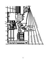
Page 37: ...Schematics Hydraulic Diagram 37 ...

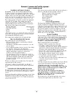
Page 38: ...r Canada customers may also call 402 223 6375 If for any reason you are dissatisfied with the Service Dealer s analysis or with the assistance provided contact us at Exmark Customer Service Department The Exmark Warranty Company 2101 Ashland Avenue Beatrice NE 68310 402 223 6375 or service exmark com Owner s Responsibilities The Exmark turf equipment including any defective part must be returned t...

Page 39: ...Notes 39 ...

Page 40: ...Notes 40 ...

Page 41: ...Service Record Date Description of Work Done Service Done By 41 ...

Page 42: ...42 ...

Page 43: ...43 ...

Page 44: ...DISPOSAL SYSTEM OUT FRONT RIDING ACCESSORIES AND OPTIONS CUSTOM RIDE SEAT SUSPENSION SYSTEM DUAL TAIL WHEEL FLOOR PAN EXTENDER HITCH KIT LIGHT KIT MICRO MULCH SYSTEM ROLL OVER PROTECTION SYSTEM ROPS SNOW BLADE SNOWBLOWER SUN SHADE TRASH CONTAINER ULTRA VAC COLLECTION SYSTEM ULTRA VAC QUICK DISPOSAL SYSTEM WEATHER CAB Place Model No and Serial No Label Here Included in the Literature Pack or Fill i...

Reviews: