background image

Figure 3

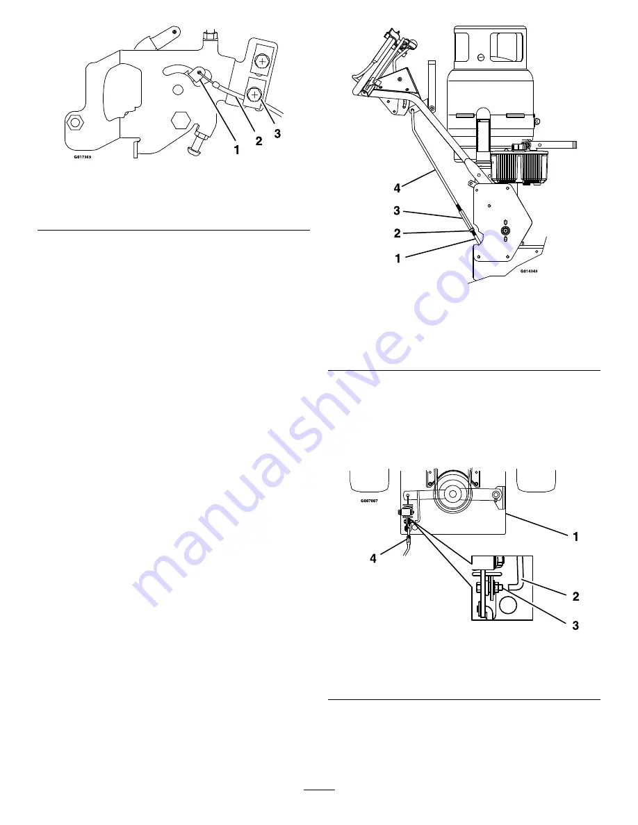
1.

Throttle control lever

3.

Clamp

2.

Throttle cable — Located
on bottom side of clamp.

Install the PTO Engagement
Linkage

1. Loosen the jam nut and remove the turnbuckle from

the lower linkage (Figure 4).

2. Screw the turnbuckle onto both the upper and the

lower linkages simultaneously. Note that threads on
upper linkage are left hand.

Note:

The handles have the drive lever linkage on

the inside of the blade engagement lever tab and the
hairpin on the outside.

Figure 4

1.

Lower PTO engagement linkage

2.

Jam nut

3.

Turnbuckle

4.

Upper PTO engagement linkage

3. With the PTO engaged, adjust the linkage length

by loosening the locknut on the turnbuckle and
adjusting the turnbuckle so that the bolt on the
bellcrank and the indicator arm align with each
other within 1/16 inch (1.6 mm) (Figure 5). Tighten
locknut against turnbuckle.

Figure 5

1.

Engine deck

3.

Align bolt to indicator
within 1/16 inch (1.6 mm)

2.

Indicator

4.

Turnbuckle

Installing the Speed Control Rod

1. Locate the speed control rod assembly with a yoke

at one end.

3

Summary of Contents for TURF TRACER X-SERIES LP Operators

Page 1: ...arranty registration form and place keys into literature pack Literature Pack Part Description Qty Use Manual Operator s 1 Read before operating the machine Manual Engine Operator s 1 Read before operating the machine Uncrating the Unit 1 Leaving the unit on the pallet place the upper handle assembly and the LP tank bracket at the rear of the machine 2 Remove the bolt bag from under the mower deck...

Page 2: ...ned to the mower The latch may require adjustment to fit the tank tightly 5 Carefully connect the fuel hose the threads are LH Make sure the hose is not kinked 6 Slowly open the fuel valve to equalize the pressure in the tank If the fuel valve is opened too quickly the pressure relief valve is equipped with a back pressure check valve that will shut off the fuel supply If this happens close the fu...

Page 3: ... engagement lever tab and the hairpin on the outside Figure 4 1 Lower PTO engagement linkage 2 Jam nut 3 Turnbuckle 4 Upper PTO engagement linkage 3 With the PTO engaged adjust the linkage length by loosening the locknut on the turnbuckle and adjusting the turnbuckle so that the bolt on the bellcrank and the indicator arm align with each other within 1 16 inch 1 6 mm Figure 5 Tighten locknut again...

Page 4: ...x 1 3 4 inch hex cap screw and a 5 8 18 inch nyloc nut on each side and tighten This will give an approximate setting for drive lever linkages Figure 6 Right Hand Side of Unit Shown 1 Drive lever linkage 2 5 16 18 inch nyloc nut 3 Speed control lever in neutral 4 Drive levers in neutral 5 5 16 18 x 1 3 4 inch hex capscrew 6 3 8 24 inch LH jam nut 7 Hydro control arm weldment 8 Lower ball joint Adj...

Page 5: ...rning Battery posts terminals and related accessories contain lead and lead compounds chemicals known to the State of California to cause cancer and reproductive harm Wash hands after handling Important The machine is shipped with a filled lead acid battery DANGER Charging the battery may produce explosive gasses Battery gasses can explode causing serious injury Keep sparks flames or cigarettes aw...

Page 6: ...ake the tire circumferences match as closely as possible Greasing the Unit Note The unit is not greased at the factory 1 Lubricate fittings with NGLI grade 2 multi purpose gun grease Refer to the following chart and Figure 8 for fitting locations and initial pumps Lubrication Chart Fitting Locations Initial Pumps Number of Places Service Interval 1 Front Caster Wheel Bearings 12 2 Daily 2 Front Ca...

Page 7: ...he HOT level shows the level of oil when it is at 225 F 107 C The COLD level shows the level of the oil when it is at 75 F 24 C Fill to the appropriate level depending upon the temperature of the oil For example If the oil is about 150 F 65 C Fill to halfway between the HOT and COLD levels If the oil is at room temperature about 75 F 24 C fill only to the COLD level Filling Out the Product Registr...

Reviews: