Maintenance
Periodic Maintenance
Check Engine Oil Level
Service Interval: Before each use or daily
1. Stop engine and wait for all moving parts to stop.
Make sure unit is on a level surface.
2. Check with engine cold.
3. Clean area around dipstick. Remove dipstick and
wipe oil off. Reinsert the dipstick and push it all
the way down into the tube.
Do Not
screw into
place. Remove the dipstick and read the oil level.
4. If the oil level is low, wipe off the area around the
oil fill cap, remove cap and fill to the “FULL”
mark on the dipstick. Exmark 4-Cycle Premium
Engine Oil is recommended; refer to the Engine
Owner’s manual for an acceptable alternative.
Do
Not
overfill.
Important:
Do Not operate the engine with the
oil level below the “LOW” (or “ADD”) mark on
the dipstick, or over the “FULL” mark.
Check Battery Charge
Service Interval: As required
WARNING
CALIFORNIA
Proposition 65 Warning
Battery posts, terminals, and related
accessories contain lead and lead
compounds, chemicals known to the State of
California to cause cancer and reproductive
harm. Wash hands after handling.
Allowing batteries to stand for an extended period of
time without recharging them will result in reduced
performance and service life. To preserve optimum
battery performance and life, recharge batteries in
storage when the open circuit voltage drops to 12.4
volts.
Note:
To prevent damage due to freezing, battery
should be fully charged before putting away for
winter storage.
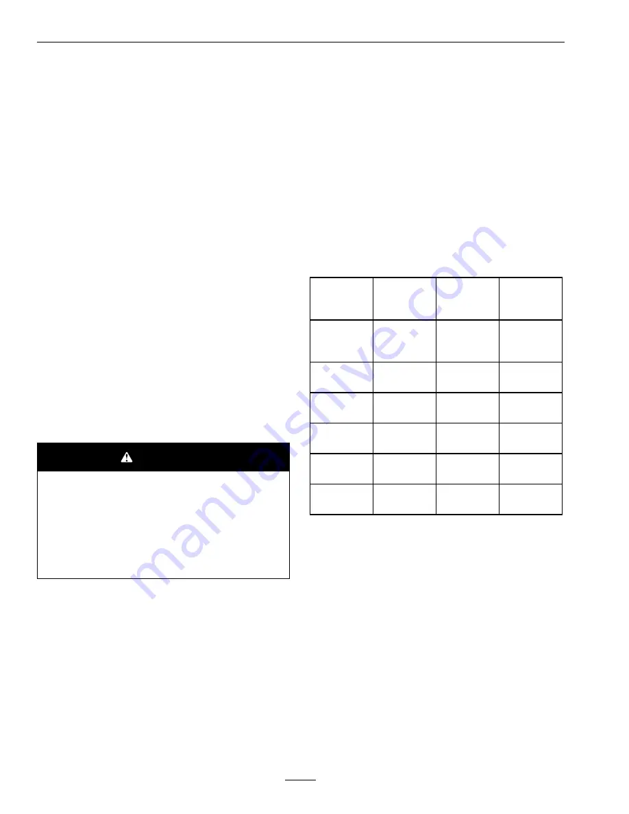
Check the voltage of the battery with a digital
voltmeter or with the message display. If the ignition
key is turned to the “on” position for a few seconds,
the battery voltage will be displayed in the area where
the hours are normally displayed. Locate the voltage
reading of the battery in the table and charge the
battery for the recommended time interval to bring
the charge up to a full charge of 12.6 volts or greater.
Important:
Make sure the negative battery cable
is disconnected and the battery charger used for
charging the battery should have an output of
16 volts and 7 amps or less to avoid damaging
the battery (see chart for recommended charger
settings). This is especially important on Kohler
EFI (Electronic Fuel Injection) units. Failure to
do so may damage the ECU (Electronic Control
Unit).
Voltage
Reading
Percent
Charge
Maximum
Charger
Settings
Charging
Interval
12.6 or
greater
100%
16 volts/7
amps
No
Charging
Required
12.4 – 12.6
75–100%
16 volts/7
amps
30 Minutes
12.2 – 12.4
50–75%
16 volts/7
amps
1 Hour
12.0–12.2
25–50%
14.4 volts/4
amps
2 Hours
11.7–12.0
0–25%
14.4 volts/4
amps
3 Hours
11.7 or less
0%
14.4 volts/2
amps
6 Hours or
More
Important:
For Kohler EFI units: Unplug the
harness from the ECU before performing any
welding on the equipment.
Recommended Jump
Starting Procedure
Service Interval: As required
1. Check the weak battery for terminal corrosion
(white, green, or blue “snow”), it must be cleaned
off prior to jump starting. Clean and tighten
connections as necessary.
24
Summary of Contents for TURF TRACER X-SERIES
Page 1: ...TURF TRACER X SERIES For Serial Nos 920 000 Higher Part No 4500 699 Rev A ...
Page 11: ...Safety 103 2242 103 2243 103 4935 103 2432 116 0404 11 ...
Page 12: ...Safety 116 4296 EFI Units Only 1 Fast 2 Slow 117 2718 12 ...
Page 38: ...Schematics Schematics Electrical Diagram All units except Kohler EFI 38 ...
Page 39: ...Schematics Electrical Diagram Kohler EFI 39 ...
Page 40: ...Schematics Electrical Logic Schematic All units except Kohler EFI 40 ...
Page 41: ...Schematics Electrical Logic Schematic Kohler EFI 41 ...
Page 42: ...Schematics Hydraulic Diagram 42 ...
Page 44: ...Notes 44 ...
Page 45: ...Service Record Date Description of Work Done Service Done By 45 ...
Page 46: ...46 ...


