- 32 -
4.2.6
Hydro Pump Spring Tension Setting
a)
For medium or heavy duty drive conditions such as operation with a sulky
on steep slopes, a higher spring force may be required on the hydro pump
control arms to prevent the drive system from stalling.
b)
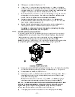
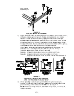
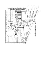
For a heavier drive setting, relocate the spring anchor link as shown in
Figure 12. The spring anchor links are located under the engine deck on
the left and right hand sides.
Note:
In “medium” or “heavy duty” positions, the drive lever forces at the
upper handle will also be increased.
FIGURE
12
HYDRO PUMP SPRING TENSION SETTING
4.2.7
Throttle Control Adjustment
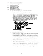
a) Loosen cable clamp on engine and position throttle control (at the control
console) within 1/4" (6 mm) from the upper end of the slot. Pull on cable
assembly at lower end where it attaches to the engine until the throttle
control arm contacts the stop screw. Secure cable with cable clamp.
b) Tension in throttle lever can be adjusted by adjusting the tightness of the
lever pivot bolt, which is located under the console. See Figure 13.
FIGURE 13
THROTTLE TENSION
4.2.8
Electric Clutch Adjustment
No adjustment necessary.
4.2.9
Park Brake Adjustment:
a)
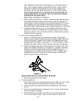
Shut off engine and wait for all moving parts to stop.
b)
Disengage the park brake.
c)
Remove the hairpin in the park brake linkage. Turn the linkage in the yoke
until there is 3/16” (.48 cm) to 1/4” (.64 cm) clearance between the park brake
tire bars and the tires with the park brake disengaged. Re-install the hairpin.
5. WASTE DISPOSAL
5.1 MOTOR OIL DISPOSAL
Engine oil and hydraulic oil are both pollutants to the environment. Dispose of used oil
at a certified recycling center or according to your state and local regulations.
Summary of Contents for Turf tracer
Page 40: ... 35 7 HYDRAULIC SCHEMATIC ...
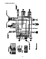
Page 41: ... 36 8 WIRING DIAGRAM ...
Page 44: ... 39 NOTES ...
Page 45: ... 40 NOTES ...
Page 46: ... 41 SERVICE RECORD Date Description of Work Done Service Done By ...


