109-3195 Rev. C
Page 8 of 9
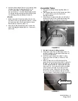
Align Dimple Here
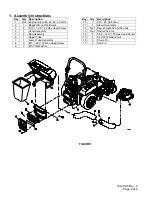
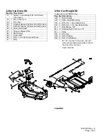
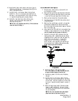
3. Install the Rear Weight (Item 12) and spacer (Item
13) from the drive kit using the (8) 5/16 – 18
X1.75 screws (Item 14) and whizlock nuts
removed in step 1. Counter Weight Spacer (Item
13) should be placed between Rear Weight (Item
12) and Bagger Mount Weldment (Item 2).
All units
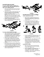
1. Slide tube ends of Hood Assembly (Item 4) into
the tubes of the mount weldment (Item 2). Install
(2) clevis pins (Item 16) through holes in tubes.
Retain with (2) Hair Pins (Item 17).
2. Hang the (2) Bag Assemblies (Item 5) from the
slots in the Bagger Upright (Item 4). Close and
latch hood.
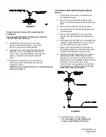
Assemble Tubes
1. Slip upper and lower tubes together (Items 6
and 7).
2. Insert upper tube (Item 6) into hopper seal (Item
4) – push in then pull out so that seal is
extended outward.
3. Align dimple on upper tube (Item 6) with end of
hopper seal and position vertically between the
two screws (Item 4) as shown in Figure 10.
FIGURE 10
4.
Set deck in lowest cutting position.
5. Slide lower tube (Item 7) onto blower (Item 11)
and latch (make sure that upper tube does not
move out of alignment).
6. Drill 7/32 holes in lower tube (Item 7) using
upper tube (Item 6) holes as reference. See
Figure 11.
7. Remove tubes from unit and assemble the
upper (Item 6) and lower tubes (Item 7) using (3)
#10-24 x .75 hex washer head screws (Item 8),
(3) #10 washers (Item 9) , and (3) #10-24 nyloc
nuts (Item 10). Screw head should be installed
to the inside of the tube to provide minimum
obstruction to flow. Make sure that the upper
and lower ends are oriented properly as tubes
are assembled. (Parting lines roughly lined up.)
FIGURE 11
Drill holes here


