background image

Operation

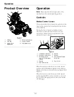
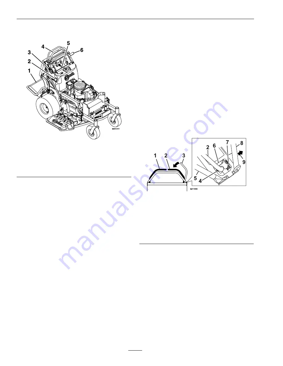
Product Overview

Figure 3

1.

Platform

4.

Motion control levers

2.

Fuel Cap

5.

Engine Controls

3.

Height-of-Cut
Adjustment

6.

Park Brake Lever

Operation

Note:

Determine the left and right sides of the

machine from the normal operating position.

Controls

Motion Control Levers

The motion control levers, located on each side of the
top console, control the forward and reverse motion
of the machine.

Moving the levers forward or backward turns
the wheel on the same side forward or reverse
respectively. Wheel speed is proportional to the
amount the lever is moved.

Figure 4

1.

LH Motion control lever

6.

Neutral

2.

RH Motion control lever

7.

Forward

3.

RH Motion control
lever in PTO disengage
position

8.

Front reference/Speed
control bar

4.

Reverse

9.

Front of unit

5.

Rear reference bar

When the motion control levers are in the neutral
position, the LCD indicator appears in the message
display on the front control console (see Figure 5 and
Figure 7).

When the motion control levers are in the neutral
position and the RH motion control lever is moved
into the PTO disengage position, the mower blades
will disengage.

16


Summary of Contents for VANTAGE S Series

Page 1: ...VANTAGE S SERIES 36 INCH MODELS For Serial Nos 316 000 000 Higher Part No 4502 635 Rev A ...

Page 2: ... The enclosed Engine Owner s Manual is supplied for information regarding The U S Environmental Protection Agency EPA and the California Emission Control Regulation of emission systems maintenance and warranty Keep this engine Owner s Manual with your unit Should this engine Owner s Manual become damaged or illegible replace immediately Replacements may be ordered through the engine manufacturer L...

Page 3: ...com for additional safe operation information such as safety tips training materials and Operator s manuals If additional information is needed or should you require trained mechanic service contact your authorized Exmark equipment dealer or distributor All Exmark equipment dealers and distributors are kept informed of the latest methods of servicing and are equipped to provide prompt and efficien...

Page 4: ...e Caster Wheel Hubs 31 Check Spark Plugs 32 Change Hydraulic System Filter and Fluid 32 Wheel Hub Nut Torque Specification 34 Check Spark Arrester if equipped 34 Thread Locking Adhesives 34 Mobil HTS Grease Or Food Grade Anti seize 34 Copper Based Anti seize 34 Dielectric Grease 34 Adjustments 35 Deck Leveling 35 Overall Height Adjustment 36 Deck Lift Handle Force 36 Pump Drive Belt Tension 36 Mow...

Page 5: ...s or mechanic s can not read this manual it is the owner s responsibility to explain this material to them other languages may be available on our website Become familiar with the safe operation of the equipment operator controls and safety signs All operators and mechanics should be trained The owner is responsible for training the users Never let children or untrained people operate or service t...

Page 6: ...ot operate without entire exhaust system in place and in proper working condition DANGER In certain conditions during fueling static electricity can be released causing a spark which can ignite gasoline vapors A fire or explosion from gasoline can burn you and others and cause property damage Always place gasoline containers on the ground away from your vehicle before filling Do Not fill gasoline ...

Page 7: ...ing or working on the mower After striking a foreign object or abnormal vibration occurs inspect the mower for damage and make repairs before restarting and operating the mower Before clearing blockages Whenever you leave the mower Stop engine wait for all moving parts to stop and engage parking brake Before refueling Before dumping the grass catcher Before making height adjustments WARNING Hands ...

Page 8: ...ngine and remove key or disconnect spark plug wire Wait for all movement to stop before adjusting cleaning or repairing Keep engine and engine area free from accumulation of grass leaves excessive grease or oil and other debris which can accumulate in these areas These materials can become combustible and may result in a fire Let engine cool before storing and do not store near flame or any enclos...

Page 9: ... the original equipment or failure to use original Exmark parts could lead to serious injury or death Unauthorized changes to the machine engine fuel or venting system may violate applicable safety standards such as ANSI OSHA and NFPA and or government regulations such as EPA and CARB WARNING Hydraulic fluid escaping under pressure can penetrate skin and cause injury Fluid accidentally injected in...

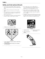
Page 10: ...quipment dealer or distributor or from Exmark Mfg Co Inc Safety signs may be affixed by peeling off the backing to expose the adhesive surface Apply only to a clean dry surface Smooth to remove any air bubbles Familiarize yourself with the following safety signs and instruction labels They are critical to the safe operation of your Exmark commercial mower 106 5517 1 Warning do not touch the hot su...

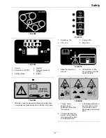
Page 11: ...t lb 75 81 N m 116 8772 1 Accessory 15A 3 Charge 25A 2 PTO 10A 4 Main 30A 116 8775 1 Read the Operator s manual 2 Fill to bottom of filler neck warning Do Not overfill the tank 121 6049 1 Thrown object hazard keep bystanders away from the machine 3 Cutting dismemberment hazard of hand or foot mower blade keep hands away from moving parts 2 Thrown object hazard mower do not operate the mower with g...

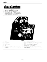
Page 12: ...s then every 500 hours thereafter 116 8819 1 Unlock 6 Grease belt idler every 500 hours 2 Forward faster 7 Grease front caster pivots and wheel bearings every 500 hours 3 Rearward slower 8 Grease linkage pivots 3 every 200 hours 4 Lock 9 Check tire pressure every 50 hours 5 Read the Operator s Manual before performing any maintenance 10 Check hydraulic oil level Only use recommended hydro oil ever...

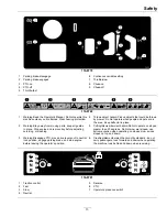
Page 13: ... keep all guards in place Stop engine and remove key before adjusting servicing or cleaning 5 Cutting dismemberment hazard Do Not operate on slopes greater than 20 degrees Do Not mow wet slopes use extreme caution when operating on slopes mow across slopes not up and down 3 Warning Disengage PTO move drive levers out to neutral lock position engage parking brake and stop engine before leaving the ...

Page 14: ...or presence in the message display on the front control panel Note Because the PTO must be disengaged to start the engine the LCD indicator will not illuminate at this time PTO must be disengaged and motion control levers in neutral to start engine It is not necessary for the operator to be on the platform to start the engine Mower blades will stop if the right side motion control lever is moved o...

Page 15: ...ch 2 5 cm to 5 inches 12 7 cm in 1 4 inch 6 4 mm increments Mulching Kit Optional Bagger Optional Dimensions Overall Width Deflector Up 39 1 inches 99 3 cm Deflector Down 48 0 inches 121 9 cm Overall Length Platform Up 61 5 inches 156 2 cm Platform Down 74 0 inches 188 0 cm Overall Height 51 5 inches 130 8 cm Tread Width Outside to Outside of Tires Widthwise 37 6 inches 95 5 cm Curb Weight 800 lb ...

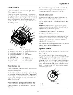
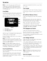
Page 16: ...n the same side forward or reverse respectively Wheel speed is proportional to the amount the lever is moved Figure 4 1 LH Motion control lever 6 Neutral 2 RH Motion control lever 7 Forward 3 RH Motion control lever in PTO disengage position 8 Front reference Speed control bar 4 Reverse 9 Front of unit 5 Rear reference bar When the motion control levers are in the neutral position the LCD indicato...

Page 17: ...re 5 The front reference speed control bar controls the maximum forward speed and is infinitely variable from approximately 4 8 mph 6 13 km hr Park Brake Lever Located on left side of unit just to the front of the LH motion control lever see Figure 5 The brake lever engages a parking brake on the drive wheels Note The LCD indicator appears in the message display on the front console when the park ...

Page 18: ...arked inside a building Align valve handle with the fuel line to open Rotate 90 to close Fuel Gauge Located on the top left side of the tank see Figure 5 The fuel gauge monitors the amount of fuel in the tank Drive Wheel Release Valves Located on the right front corner of the hydrostatic pumps Drive wheel release valves are used to release the hydrostatic drive system to allow the machine to be mo...

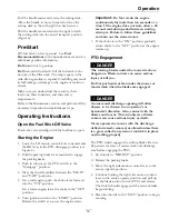
Page 19: ... OFF position 6 Turn ignition switch to the START position Release the switch as soon as the engine starts Important Do Not crank the engine continuously for more than ten seconds at a time If the engine does not start allow a 60 second cool down period between starting attempts Failure to follow these guidelines can burn out the starter motor 7 If the choke is in the ON position gradually return ...

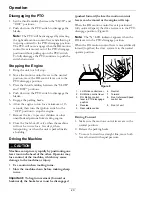
Page 20: ...ot be in use for a few days when transporting or when the unit is parked inside a building Driving the Machine CAUTION Machine can spin very rapidly by positioning one lever too much ahead of the other Operator may lose control of the machine which may cause damage to the machine or injury Use caution when making turns Slow the machine down before making sharp turns Important To begin movement for...

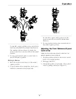
Page 21: ... move rearward in a straight line slowly move both levers rearward with equal pressure Figure 10 To turn left or right release pressure on the motion control lever toward the desired turn direction 3 To stop position both motion control levers in the neutral operate position Adjusting the Front Reference Speed Control Bar Adjust the front reference speed control bar for desired maximum forward spe...

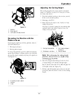
Page 22: ... not supported when the latch pin is pulled out Do Not put your hands or fingers in the platform pivot area when lowering or raising the operator platform Make sure the platform is supported when the latch pin is pulled out Make sure the latch secures the platform when folding it in the up position Push it tight against the cushion for the latch pin to lock into place Operating the Machine with th...

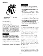
Page 23: ... Stop the machine and move the motion control levers to the neutral position 2 Disengage the PTO 3 Raise and lock the deck to the 5 inch 12 7 cm transport position The deck is raised by pulling the deck lift handle rearward and to the right to place it into the transport lock position Figure 14 1 Transport lock position 3 Front reference speed control bar 2 RH Motion control lever 4 Deck lift hand...

Page 24: ...nbroken ramp surface wider than the unit Do Not exceed a 20 degree angle between ramp and ground or between ramp and trailer or truck Avoid sudden acceleration while driving unit up a ramp to avoid tipping backward Avoid sudden deceleration while backing unit down a ramp to avoid tipping backward Loading a Unit Use extreme caution when loading units on trailers or trucks One full width ramp that i...

Page 25: ...each use or daily Check the engine oil level Check the mower blades Check the safety interlock system Check for loose hardware Clean the engine and exhaust system area Clean the grass and debris build up from the machine and cutting deck Clean the grass build up from under the deck Every 40 hours Check the hydraulic oil level Check the condition of the belts Every 50 hours Check the tire pressures...

Page 26: ...nd lead compounds chemicals known to the State of California to cause cancer and reproductive harm Wash hands after handling Allowing batteries to stand for an extended period of time without recharging them will result in reduced performance and service life To preserve optimum battery performance and life recharge batteries in storage when the open circuit voltage drops to 12 4 volts Note To pre...

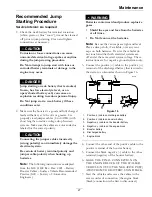
Page 27: ...ng instructions are adapted from the SAE J1494 Rev Dec 2001 Battery Booster Cables Surface Vehicle Recommended Practice SAE Society of Automotive Engineers WARNING Batteries contain acid and produce explosive gases Shield the eyes and face from the batteries at all times Do Not lean over the batteries Note Be sure the vent caps are tight and level Place a damp cloth if available over any vent caps...

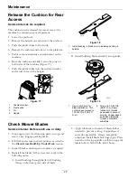
Page 28: ... brake 2 Lift deck and secure in raised position as stated in the Clean Grass Build Up Under Deck section 3 Inspect blades and sharpen or replace as required 4 Reinstall the blades if they were removed in the following order A Install bushing through blade with bushing flange on bottom grass side of blade Figure 18 1 Install bushing in blade prior to installing bushing in spindle B Install bushing...

Page 29: ...art the engine and release the parking brake 5 Move the right side motion control lever to the center operating position 6 Continue holding the right side motion control lever in the center operating position and pull up on the blade control switch PTO and release The clutch should engage and the mower blades begin rotating 7 Move or release the right side motion control lever into the neutral pos...

Page 30: ...Stop engine and recheck oil level 7 Wipe up any spilled oil from engine deck mounting surfaces Check Hydraulic Oil Level Service Interval Every 40 hours 1 Stop engine and wait for all moving parts to stop and remove key Engage parking brake 2 Clean area around hydraulic reservoir cap and remove cap Oil level should be to the top of the baffle inside the tank If not add oil Use Exmark Premium Hydro...

Page 31: ... caster wheel Note that thread locking adhesive has been applied to lock the spacer nuts to the axle Remove the axle with the other spacer nut still assembled to it from the wheel assembly 5 Pry out seals and inspect bearings for wear or damage and replace if necessary 6 Pack the bearings with a NGLI grade 1 multi purpose grease 7 Insert one bearing one new seal into the wheel Note Seals Exmark P ...

Page 32: ...h pan under the hydro 3 Carefully clean area around filter It is important that no dirt or contamination enter hydraulic system 4 Unscrew filter to remove and allow oil to drain from reservoir Important Before reinstalling new filter fill it with Exmark Premium Hydro oil and apply a thin coat of oil on the surface of the rubber seal Turn filter clockwise until rubber seal contacts the filter adapt...

Page 33: ...he drive wheels off the ground 2 Check oil level as stated in Check Hydraulic Oil Level section 3 Start engine and move throttle control ahead to full throttle position Move RH motion control lever inward together and move both levers forward with equal pressure If either drive wheel does not rotate it is possible to assist the purging of the charge pump by carefully rotating the tire in the forwa...

Page 34: ... observed remove arrester and shake loose particles out of the arrester and clean screen with a wire brush soak in solvent if necessary Reinstall arrester on exhaust outlet Thread Locking Adhesives Thread locking adhesives such as Loctite 242 or Fel Pro Pro Lock Nut Type are used on the following fasteners Pump sheave setscrews Sheave retaining bolt in end of engine crankshaft Caster wheel spacer ...

Page 35: ...e 3 Check the air pressure in the drive tires If needed adjust to the recommended inflation refer to Checking the Tire Pressure in Drive System Maintenance section 4 Set the height of cut lever to the 3 inch 7 6 cm position 5 Raise the discharge deflector 6 Carefully rotate the blades front to rear Measure from the tip of the front blade to the level surface Figure 22 The blades should measure 3 i...

Page 36: ... right side of the machine see Figure 24 Figure 24 1 Jam nuts 2 Height of cut adjustment rod 7 Loosen the jam nuts and turn the adjustment rod until the blade tips match 3 inches 7 6 cm 8 Tighten jam nuts Deck Lift Handle Force Tighten or loosen the bolt to adjust the amount of force it takes to move the deck lift handle Turning the bolt clockwise transfers some of the deck weight from the lift ha...

Page 37: ...ature 5 Brake spacer 2 Field shell 6 Re gap shim 3 Rotor 7 Brake pole 4 Brake mounting bolt Removing the Shim 1 Stop engine wait for all moving parts to stop and remove key Engage parking brake Allow the machine to cool completely before starting these instructions 2 Using a pneumatic line blow out any debris from under the brake pole and around the brake spacers 3 Check the condition of the wire ...

Page 38: ...nt proceed to the safety check in step F F Perform the following safety check a Sit on the seat and start the engine b Make sure the blades Do Not engage with the PTO switch off and the clutch disengaged If the clutch does not disengage reinstall the shim and reference the Troubleshooting section c Engage and disengage the PTO switch ten consecutive times to ensure the clutch is functioning proper...

Page 39: ...on Control Tracking Adjustment If the machine travels or pulls to one side when the motion control levers are in the full forward position adjust the tracking 1 Push both control levers forward the same distance 2 Check if the machine pulls to one side If it does stop the machine and set the parking brake 3 Release the rear cushion from the rear of the machine 4 Place the front reference speed con...

Page 40: ...e right motion control lever horizontally the cam needs to be adjusted 5 Release the cushion from the rear of the machine 6 Loosen the nut holding the cam see Figure 35 Figure 35 1 Cam 2 Nut 7 Adjust the cam until it aligns with the left motion control lever and tighten the nut for the cam Note Moving the flat portion of the cam clockwise lowers the handle while moving it counterclockwise raises t...

Page 41: ...em area 3 Wipe up any excessive grease or oil around the engine and exhaust system area Remove Engine Shrouds and Clean Cooling Fins Service Interval Every 80 hours 1 Stop engine wait for all moving parts to stop and remove key Engage parking brake 2 Remove cooling shrouds from engine and clean cooling fins Also clean dust dirt and oil from external surfaces of engine which can cause improper cool...

Page 42: ...aste Disposal Motor Oil Disposal Engine oil and hydraulic oil are both pollutants to the environment Dispose of used oil at a certified recycling center or according to your state and local regulations Battery Disposal DANGER Battery electrolyte contains sulfuric acid which is poisonous and can cause severe burns Swallowing electrolyte can be fatal or if it touches skin can cause severe burns Wear...

Page 43: ...ct an Authorized Service Dealer 1 Fuel tank is empty 1 Fill the fuel tank 2 Fuel shutoff valve is closed 2 Open the fuel shutoff valve 3 The throttle and choke are not in the correct position 3 Be sure the throttle control is midway between the SLOW and FAST positions and the choke is in the ON position for a cold engine or the OFF position for a warm engine 4 Dirt in fuel filter 4 Replace the fue...

Page 44: ...e pressure in drive tires not correct 5 Adjust tire pressure in the drive tires 6 Blade spindle bent 6 Contact an Authorized Service Dealer Uneven cutting height 7 Tips of adjacent blades are at an uneven cutting height Blades tips should be even within 3 16 inch which is approximately one blade thickness 7 Replace blades spindles and or check for damage to mower deck 1 Cutting blade s is are bent...

Page 45: ...cessary 2 Low voltage supply at the clutch 2 Check coil resistance battery charge charging system and wiring connections and replace if necessary 3 Damaged coil 3 Replace clutch 4 Inadequate current supply 4 Repair or replace clutch lead wire or electrical system Clean connector contacts Clutch will not engage 5 Rotor armature airgap is too large 5 Remove shim or replace clutch 45 ...

Page 46: ...Schematics Schematics Electrical Diagram 46 ...

Page 47: ...Schematics Electrical Schematic 47 ...

Page 48: ...Schematics Hydraulic Diagram 48 ...

Page 49: ...ystem coverage All warranty work must be performed by an authorized Exmark Service Dealer using Exmark approved replacement parts Instructions for Obtaining Warranty Service The product must be registered with original proof of purchase by an Exmark Service Dealer before obtaining any warranty service Contact any Exmark Service Dealer to arrange service at their dealership To locate a dealer conve...

Page 50: ...50 ...

Page 51: ...se the slope indicator to determine the degree of slope of hills before operating Do Not operate this machine on a slope greater than 20 degrees Fold along the appropriate line to match the recommended slope 2 Align this edge with a vertical surface a tree building fence pole etc 3 Example of how to compare slope with folded edge 51 ...

Page 52: ... RIDE SEAT SUSPENSION SYSTEM DUAL TAIL WHEEL FLOOR PAN EXTENDER HITCH KIT LIGHT KIT MICRO MULCH SYSTEM ROLL OVER PROTECTION SYSTEM ROPS SNOW BLADE SNOWBLOWER SUN SHADE TRASH CONTAINER ULTRA VAC COLLECTION SYSTEM ULTRA VAC QUICK DISPOSAL SYSTEM WEATHER CAB Some accessories and options not available for some models Place Model No and Serial No Label Here Included in the Literature Pack or Fill in Be...

Reviews: