Operation
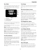
Hour Meter
Located on the LH side of the front control console
in the message display (see Figure 5 and Figure 7).
The hour meter records the number of hours that
the engine has run.
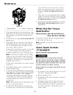
Figure 7
1.
LCD Indicators
2.
Low voltage indicator light
3.
Hour/Voltage display
The hour meter is recording when the decimal point
is flashing in Hour/Voltage display.
Hours are displayed when the key is off or when the
machine is running.
Note:
If the ignition key is turned to the “ON”
position for a few seconds before cranking the engine,
the battery voltage will display in the area where the
hours are normally displayed.
Note:
The LCD indicators appear when each
control meets the “safe to start” mode. Because the
PTO must be disengaged to start the engine, the
LCD indicator will not illuminate at this time.
Fuel Shut-Off Valve
Located on the RH side of the control tower behind
the knee cushion for Kawasaki units. Located on
the LH side of the machine, towards the rear of the
engine, on Kohler units.
The fuel shut-off valve is used to shut off the fuel
when the machine will not be used for a few days,
during transport to and from the jobsite, and when
parked inside a building.
Align valve handle with the fuel line to open. Rotate
90° to close.
Fuel Gauge
Located on the top left side of the tank (see Figure 5).
The fuel gauge monitors the amount of fuel in the
tank.
Drive Wheel Release Valves
Located on the right front corner of the hydrostatic
pumps.
Drive wheel release valves are used to release the
hydrostatic drive system to allow the machine to be
moved by hand without the engine running.
With a 5/8 wrench, turn both valves one turn
counterclockwise to release the drive system.
Turn clockwise to reset the drive system. Torque to
110-130 in-lb (12-15 N-m).
Do Not overtighten.
Do Not tow machine.
PTO Engagement Switch
Located on front control panel (see Figure 5).
Switch must be pulled out (up) to engage the blades.
Switch is pushed in to disengage the blades.
The LCD indicator will appear when the PTO switch
is engaged (see Figure 7).
Low Voltage Indicator
Located on the front control panel in the message
display (see Figure 5 and Figure 7).
A low voltage condition (less than 12.3 volts) exists
when the low voltage indicator light appears on the
message display while the engine is running.
If the ignition key is turned to the “ON” position for
a few seconds before cranking the engine, the battery
voltage will display in the area where the hours are
normally displayed.
Note:
The indicator normally appears when the
engine is off and the key switch is turned to the
“ON” position.
Deck Lift Handle
Located on the RH of the front control panel.
Pull the handle rearward to raise the cutting deck.
Allow the handle to move forward to lower the
cutting deck to the cut height that has been set.
21
Summary of Contents for VANTAGE X Series
Page 1: ...VANTAGE X SERIES For Serial Nos 315 000 000 Higher Part No 4502 224 Rev A ...
Page 51: ...Schematics Schematics Electrical Diagram All Units Except Kohler EFI 51 ...
Page 52: ...Schematics Electrical Diagram Kohler EFI 52 ...
Page 53: ...Schematics Electrical Schematic All Units Except Kohler EFI 53 ...
Page 54: ...Schematics Electrical Schematic Kohler EFI 54 ...
Page 55: ...Schematics Hydraulic Diagram 55 ...
Page 57: ...Service Record Date Description of Work Done Service Done By 57 ...
Page 58: ...58 ...

