Maintenance
G011733
1
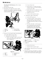
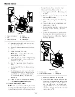
Figure 31
1.
Feeler gauge
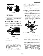
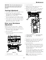
Figure 32
1.
Feeler gauge
•
If the gap is less than 0.010 inch, then
reinstall the shim and reference the
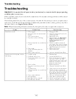
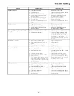
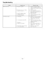
Troubleshooting
section.
•
If the gap is sufficient, proceed to the
safety check in step F.
F. Perform the following safety check:
a. Sit on the seat and start the engine.
b. Make sure the blades Do Not engage with
the PTO switch “off ” and the clutch
disengaged.
If the clutch does not disengage,
reinstall the shim and reference the
Troubleshooting
section.
c. Engage and disengage the PTO switch
ten consecutive times to ensure the clutch
is functioning properly. If the clutch
does not engage properly, reference the
Troubleshooting
section.
Neutral Adjustment
If the machine travels or the LCD indicator light
does not illuminate when the speed control lever is in
neutral, then an adjustment is required.
1. Stop engine and wait for all moving parts to
stop. Engage parking brake. Raise the rear of the
machine up onto jack stands high enough to raise
the drive wheels off of the ground.
2. Release the rear cushion from the rear of the
machine.
A.
Check the speed control linkage and
neutral safety switch:
a. With the engine off, turn the ignition
switch to the “ON” position.
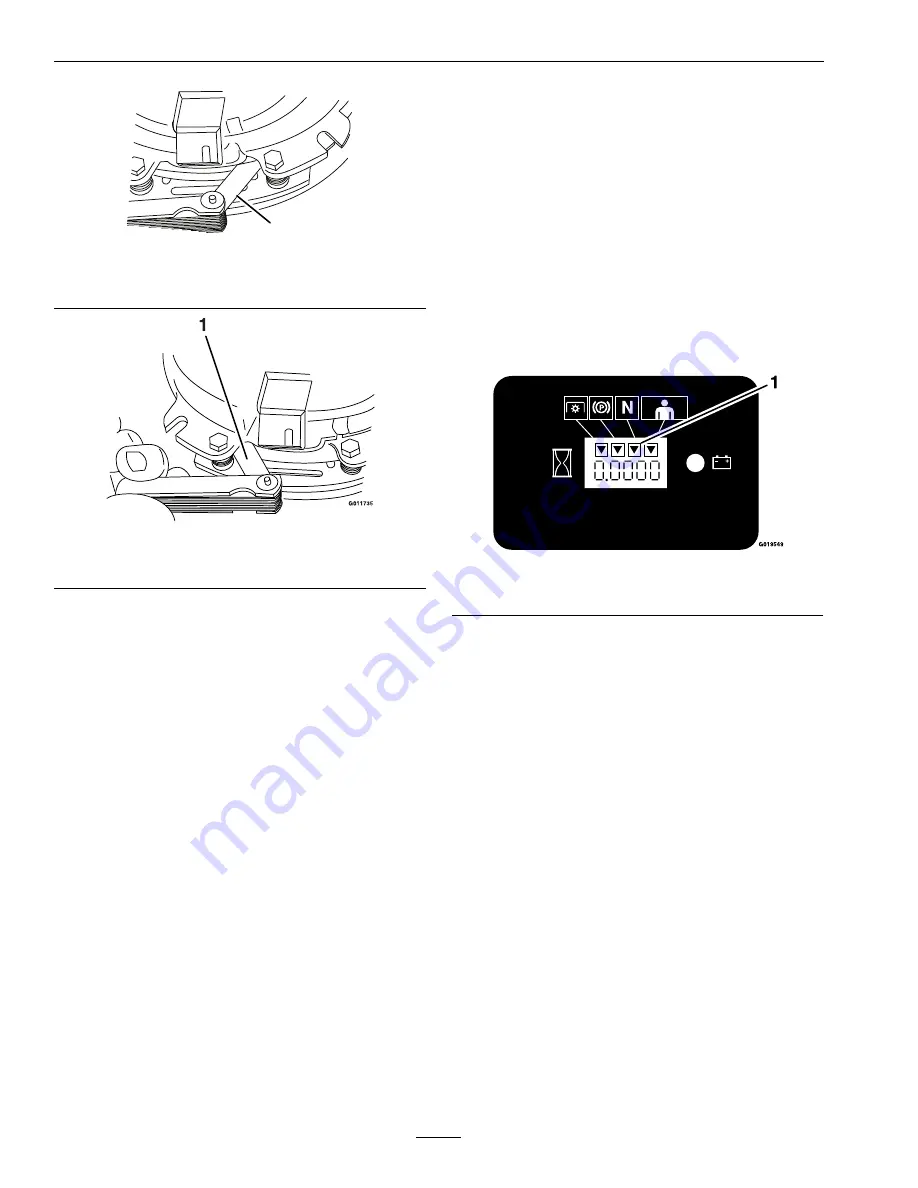
b. Locate the LCD indicator in the message
display.
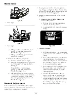
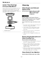
Figure 33
1.
Neutral LCD indicator
c. With the speed control lever in the neutral
position, the neutral LCD indicator should
appear.
d. If the indicator illuminates, push the lever
ahead; the indicator should disappear
within 3/4 inch (19 mm) amount of travel.
If it exceeds this distance, an adjustment
to the neutral switch is required.
e. If the indicator does not illuminate, with
the speed control lever in the full back
position, an adjustment to the neutral
switch is required.
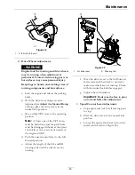
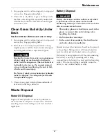
f. Pull the speed control lever back to
neutral. Check that the neutral safety
switch actuating tab has depressed the
plunger of the switch so that there is about
11/32 inch (8.6 mm) between the tab and
the switch (see Figure 34). If necessary,
move the switch fore and aft.
42
Summary of Contents for VANTAGE X Series
Page 1: ...VANTAGE X SERIES For Serial Nos 315 000 000 Higher Part No 4502 224 Rev A ...
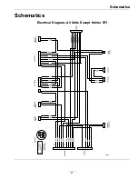
Page 51: ...Schematics Schematics Electrical Diagram All Units Except Kohler EFI 51 ...
Page 52: ...Schematics Electrical Diagram Kohler EFI 52 ...
Page 53: ...Schematics Electrical Schematic All Units Except Kohler EFI 53 ...
Page 54: ...Schematics Electrical Schematic Kohler EFI 54 ...
Page 55: ...Schematics Hydraulic Diagram 55 ...
Page 57: ...Service Record Date Description of Work Done Service Done By 57 ...
Page 58: ...58 ...

