UK |
17
3112007_RSG_UK
Electrical installation
The fan is variably adjustable.
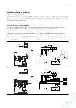
All Exodraft fans require extra safeguards in accordance with power current regulations. For further details,
please see guidelines for the Exodraft control units.The diagrams shows the connection of the 6-core cable
in the terminal box on the motor.
Setting up the isolation switch:
In accordance with the provisions of the EU Machinery Directive* a chimney fan must always have an
isolation switch fitted. The isolation switch must comply with national wiring standards.
The isolation switch must be ordered separately, as it is not part of the standard Exodraft chimney fan
delivery.
*Please refer to Machine Directive (2006/42/EF/-EEC/-EWG/-CEE) – Appendix 1 item 1.6.3 “Separation of the sources of energy”
Exodraft motor
Grundfos motor
8
7
6
5
4
3
2
1
AUX
MAIN
P
BN
BK
BU
4
5
3
1
2
1
2
3
4
NO
NC
C
N
L1
5
YEGN
POWER SUPPLY
1 x 230 V ~ 50 Hz
6 x 0,75
BK
BN
BU
3 x 0,75
YEGN
8
7
6
5
4
3
2
1
AUX
MAIN
t°
P
BN
BK
BU
4
5
3
1
2
1
2
3
4
NO
NC
C
N
L1
5
YEGN
POWER SUPPLY
1 x 230 V ~ 50 Hz
6 x 0,75
BK
BN
BU
3 x 0,75
YEGN


