background image

7

WARNING:

If  any  parts  are  damaged  or  missing,  do  not  operate 

this tool until the parts are replaced. Failure to heed this 

warning could result in serious personal injury.

WARNING:

Do  not  attempt  to  modify  this  tool  or  create  accesso-

ries not recommended for use with this tool. Any such 

alteration or modification is misuse and could result in a 

hazardous condition leading to possible serious personal 

injury.

WARNING:

Do not connect to power head until assembly is complete. 
Failure to comply could result in accidental starting and 
possible serious personal injury.

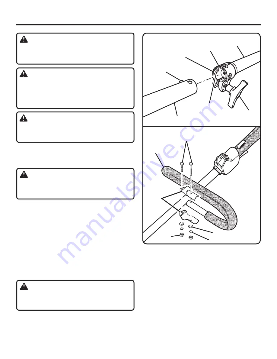
JOINING THE POWER HEAD TO THE 
BRUSHCUTTER ATTACHMENT

See Figure 2.

WARNING: 

Never attach or adjust any attachment while power head 

is running. Failure to stop the engine may cause serious 

personal injury.

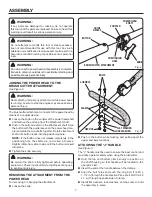
The brushcutter attachment connects to the power head by 
means of a coupler device. 

  Loosen the knob on the coupler of the power head shaft 

and remove the end cap from the attachment shaft.

  Push in the button located on the attachment shaft. Align 

the button with the guide recess on the power head cou-
pler and slide the two shafts together. Rotate attachment 
shaft until button locks into the positioning hole.

  NOTE: If the button does not release completely in the 

positioning  hole,  the  shafts  are  not  locked  into  place. 
Slightly rotate from side to side until the button is locked 
into place.

  Tighten the knob securely. 

WARNING: 

Be certain the knob is fully tightened before operating 

equipment. Check it periodically for tightness during use 

to avoid serious injury.

REMOVING THE ATTACHMENT FROM THE 
POWER HEAD

For removing or changing the attachment:

  Loosen the knob.

  Push in the button while twisting and pulling apart the 

upper and lower sections.

ATTACHING THE “J” HANDLE

See Figure 3.

The “J” handle must be used to ensure the best control and 
maximize operator safety when using the brushcutter.

  Hold  the  top  and  bottom  clamp  snugly  in  position  on 

the shaft housing so that handle will be located to the 
operator’s left.

  Insert the end of the handle between the clamps.

  Align  the  bolt  holes  and  push  the  long  bolt  (1/4-20  x  

1-1/2 in.) through the handle side. Place short bolt (1/4-20 
x 1 in.) through opposite side of clamp. 

  Install flat washers, lock washers, and hex nuts to hold 

the assembly in place.

ASSEMBLY

Fig. 2

KNOB

COUPLER

BRUSHCUTTER ATTACHMENT

POWER HEAD 

SHAFT

POSITIONING 

HOLE

GUIDE  

RECESS

BUTTON

Fig. 3

CLAMP

FLAT WASHER

LOCK WASHER

HEX NUT

J-HANDLE

BOLTS

Summary of Contents for Expand-it UT15702B

Page 1: ...n engineered and manufactured to a high standard for dependability ease of operation and operator safety Properly cared for it will give you years of rugged trouble free performance Thank you for buyi...

Page 2: ...8 9 Maintenance 10 Exploded View and Parts List 11 Warranty 12 Parts Ordering and Service Back page This product has many features for making its use more pleasant and enjoyable Safety performance an...

Page 3: ...injury Always stop the engine and remove the spark plug wire or disconnect from power supply before mak ing any adjustments or repairs except for carburetor adjustments Inspect unit before each use fo...

Page 4: ...any other blade To install any other brand blade or cutting head to this brushcutter can result in serious personal injury The TRI ARC blade is suited for cutting thicker weeds or pulpy stalks only Do...

Page 5: ...INSTRUCTIONS The following signal words and meanings are intended to explain the levels of risk associated with this product SYMBOL SIGNAL MEANING Indicates an imminently hazardous situation which if...

Page 6: ...EAD END CAP J HANDLE ASSEMBLY SHOULDER HARNESS ASSEMBLY ASSEMBLY UNPACKING This product requires assembly Carefully remove the items from the box Make sure that all items listed in the packing list ar...

Page 7: ...ttachment shaft until button locks into the positioning hole NOTE If the button does not release completely in the positioning hole the shafts are not locked into place Slightly rotate from side to si...

Page 8: ...your eyes resulting in possible serious injury WARNING Do not use any attachments or accessories not recommended by the manufacturer of this tool The use of attachments or accessories not recommended...

Page 9: ...ker weeds and pulpy stalks When the blade becomes dull it can be turned over to extend the life of the blade Do not sharpen the TRI ARC blade Use only TRI ARC blade part number 06297 available at your...

Page 10: ...washer and gear head Remove the blade nut by turning it clockwise left handed threads Remove the cupped washer and the blade To install blade Place flanged washer over the gear shaft with the hollow s...

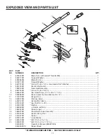
Page 11: ...Hex Head Screw 1 4 in 20 x 1 1 4 in 1 10 000998233 Boom Assembly Includes Key No 12 1 11 518019001 Hanger Cap 1 12 940657004 Warning Label 1 13 638014001 Handle Bar Clamp 2 14 678016001 Hex Nut 1 4 in...

Page 12: ...warranty does not extend to repairs made necessary by normal wear or by the use of parts or accessories which are either incompatible with the EXPAND IT brand product or adversely affect its operatio...

Page 13: ...13 NOTES...

Page 14: ...vide all relevant information when you call or visit For the location of the authorized service center nearest you please call 1 800 242 4672 or visit us online at www homelite com REPAIR PARTS The mo...

Reviews: