background image

8

ASSEMBLY

  After  assembly  is  complete,  adjust  the  position  of  the 

handle for best balance and comfort.

  Tighten the long bolt, then the short bolt.

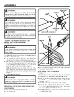
INSTALLING THE SHOULDER HARNESS AND 
STRAP HANGER

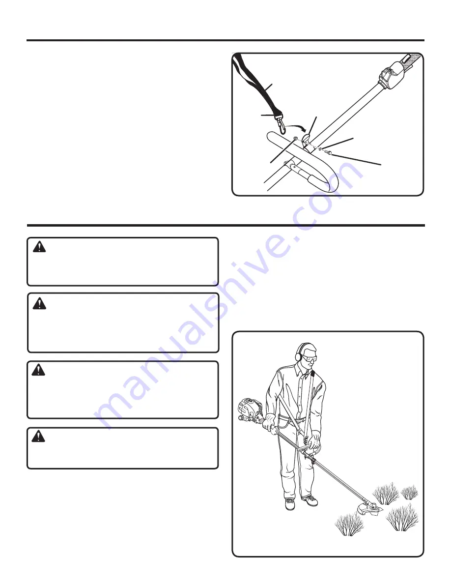
See Figure 4.


  Pull  apart  the  ends  of  the  shoulder  harness  hanger  to 

expand slightly.

  Slide the hanger over the power head shaft immediately 

behind the “J” handle.

  Squeeze hanger ends together to retighten.

  Install the bolt, lock washer, and lock nut to secure.

  Connect the latch on the shoulder harness to the strap 

hanger.

WARNING:

Do not allow familiarity with tools to make you careless. 
Remember  that  a  careless  fraction  of  a  second  is 
sufficient to inflict serious injury.

WARNING:

Always wear safety goggles or safety glasses with side 
shields  when  operating  power  tools.  Failure  to  do  so 
could  result  in  objects  being  thrown  into  your  eyes 
resulting in possible serious injury.

WARNING:

Do  not  use  any  attachments  or  accessories  not 
recommended by the manufacturer of this tool. The use 
of  attachments  or  accessories  not  recommended  can 
result in serious personal injury.

WARNING:

To avoid burns from hot surfaces, never operate unit with 

the bottom of the engine above waist level.

APPLICATIONS

You may use this tool for the purpose listed below:

  Cutting areas which cannot be reached with other types 

of mowing equipment

Fig. 4

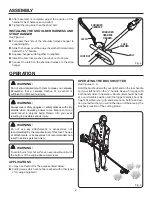
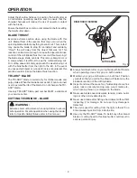
OPERATING THE BRUSHCUTTER

See Figures 5 - 6.

Hold the brushcutter with your right hand on the rear handle 
and your left hand on the “J” handle. Keep a firm grip with 
both hands while in operation. Brushcutter should be held 
at a comfortable position with the trigger handle about hip 
height. Maintain your grip and balance on both feet. Posi-
tion yourself so that you will not be drawn off balance by the 
kickback reaction of the cutting blade. 

SHOULDER 

HARNESS

SHOULDER 

HARNESS 

HANGER

BOLT

LOCK 

WASHER

LOCK NUT

OPERATION

Fig. 5

LATCH

Summary of Contents for Expand-it UT15702B

Page 1: ...n engineered and manufactured to a high standard for dependability ease of operation and operator safety Properly cared for it will give you years of rugged trouble free performance Thank you for buyi...

Page 2: ...8 9 Maintenance 10 Exploded View and Parts List 11 Warranty 12 Parts Ordering and Service Back page This product has many features for making its use more pleasant and enjoyable Safety performance an...

Page 3: ...injury Always stop the engine and remove the spark plug wire or disconnect from power supply before mak ing any adjustments or repairs except for carburetor adjustments Inspect unit before each use fo...

Page 4: ...any other blade To install any other brand blade or cutting head to this brushcutter can result in serious personal injury The TRI ARC blade is suited for cutting thicker weeds or pulpy stalks only Do...

Page 5: ...INSTRUCTIONS The following signal words and meanings are intended to explain the levels of risk associated with this product SYMBOL SIGNAL MEANING Indicates an imminently hazardous situation which if...

Page 6: ...EAD END CAP J HANDLE ASSEMBLY SHOULDER HARNESS ASSEMBLY ASSEMBLY UNPACKING This product requires assembly Carefully remove the items from the box Make sure that all items listed in the packing list ar...

Page 7: ...ttachment shaft until button locks into the positioning hole NOTE If the button does not release completely in the positioning hole the shafts are not locked into place Slightly rotate from side to si...

Page 8: ...your eyes resulting in possible serious injury WARNING Do not use any attachments or accessories not recommended by the manufacturer of this tool The use of attachments or accessories not recommended...

Page 9: ...ker weeds and pulpy stalks When the blade becomes dull it can be turned over to extend the life of the blade Do not sharpen the TRI ARC blade Use only TRI ARC blade part number 06297 available at your...

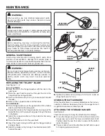
Page 10: ...washer and gear head Remove the blade nut by turning it clockwise left handed threads Remove the cupped washer and the blade To install blade Place flanged washer over the gear shaft with the hollow s...

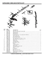
Page 11: ...Hex Head Screw 1 4 in 20 x 1 1 4 in 1 10 000998233 Boom Assembly Includes Key No 12 1 11 518019001 Hanger Cap 1 12 940657004 Warning Label 1 13 638014001 Handle Bar Clamp 2 14 678016001 Hex Nut 1 4 in...

Page 12: ...warranty does not extend to repairs made necessary by normal wear or by the use of parts or accessories which are either incompatible with the EXPAND IT brand product or adversely affect its operatio...

Page 13: ...13 NOTES...

Page 14: ...vide all relevant information when you call or visit For the location of the authorized service center nearest you please call 1 800 242 4672 or visit us online at www homelite com REPAIR PARTS The mo...

Reviews: