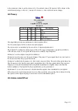
The Z knob/CV sets the speed of the simulation i.e. the rate at which the outputs change.
Parameter 0 sets the range of speed values attainable, in quarter octaves (i.e. raising the value by 4
doubles the speed).
Parameters 2 & 3 are attenuverters for outputs A & B.
Parameters 4 & 5 are offsets for outputs A & B (with a range of ±8V).
Parameter 6 enables a clamp, in the event that the simulation becomes numerically unstable, in
which case it is reset to initial conditions. With the clamp disabled, the simulation can generate
extreme values, which have nothing to do with the Lorenz equations but are potentially useful in
their own right.
Pushing Z resets the simulation to initial conditions.
N-1 Switch
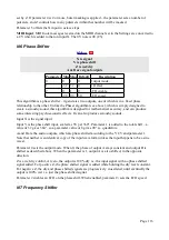
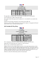
X and Y are inputs
A and B are outputs
Z is control CV or trigger
Knob recorder enabled
Parameter Min Max Default
Description
0
0
1
0
Mode.
1
0
32
3
Hysteresis.
2
0
99
0
Fade.
3
-1
99
99
Chance.
This algorithm is a voltage controlled or triggered crossover switch. That is, either
X → A and Y → B
or
X → B and Y → A
Note that by using only one input, the algorithm effectively directs an input to one of two outputs
(e.g. X to either A or B); likewise, using only one output, the algorithm chooses between two inputs
(e.g. A is either X or Y).
Being fully DC-coupled, the algorithm can be used for switching either audio or CV.
Parameter 0 chooses the mode – whether the Z knob/CV is a direct switch or a trigger.
In mode 0, Z is a switch. The switch occurs at 0V. Hysteresis can be applied to the switching
voltage with parameter 1.
In mode 1, Z is a trigger. A positive-going input edge toggles the switch.
When using an external CV as a switch or trigger, you may like to turn the Z knob slightly
counterclockwise.
A crossfade can be applied when switching to avoid clicks. The length of the fade (in milliseconds)
is controlled by parameter 2.
Parameter 3 sets the probability that a switch transition will actually occur when triggered. Add one
Page 112


