Signal flow
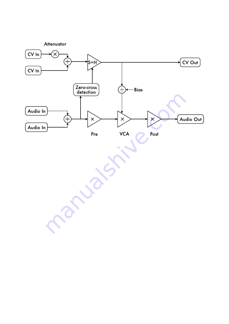
The diagram below shows the module's operation in outline:
Audio path
The two audio inputs are summed (mixed), and then pass through three gain stages: the Pre
stage (i.e. pre-VCA), the VCA itself, and the Post stage. The purpose of the Pre stage is primarily
to reduce the input level to one that the VCA can handle with reasonable linearity; likewise the
main purpose of the Post stage is to boost the signal back to normal levels. Conversely, by
deliberately raising the gain of the Pre stage we can deliberately operate the VCA in its non-
linear (saturating) region; then the purpose of the Post stage becomes that of reducing the level
so it doesn't clip at the output.
The Asymmetry switch disables part of the circuit that linearises the behaviour of the VCA,
resulting in positive and negative sections of the input waveform being processed quite
diferently, increasing the even harmonic distortion.
The whole audio path is DC coupled.
CV path
The two CV inputs are summed, one via the attenuator, and passed to a Sample-And-Hold
circuit. If the zero-cross detection is not enabled, this simply passes the CV straight through. If
the zero-cross detection is enabled, the CV is sampled whenever the audio signal passes through
zero, and that CV value is held in between zero-crosses.
The CV output is the output of the S
+
H circuit.
The Bias is added to the CV from the S
+
H and the result is used as the controlling voltage of the
VCA.


