EXPERT Standard Series User Manual
196
If FC.24=341, set the terminal control mode to bind AI1 analog given, set the operation
panel control mode to bind digital setting 1, and set the serial port control mode to bind
digital setting 3.
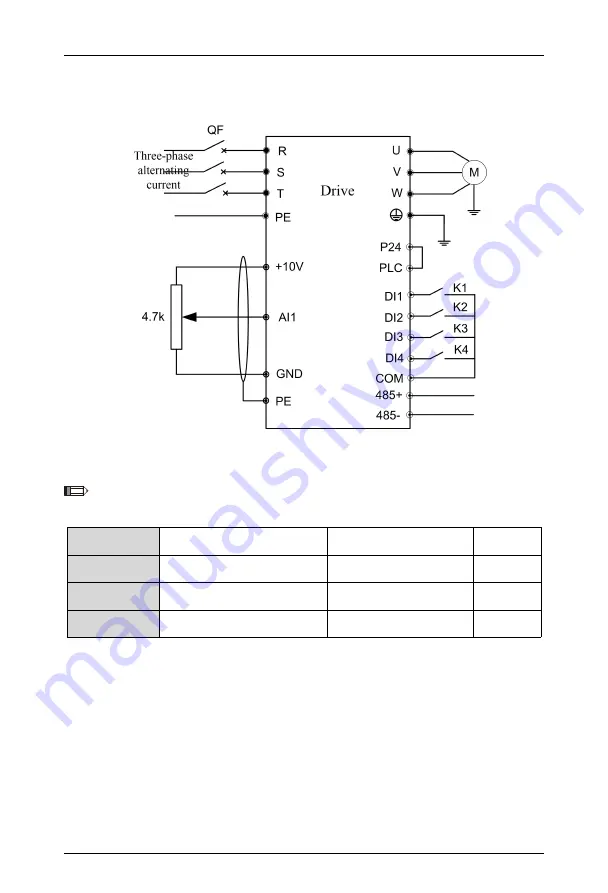
Figure 6-65 Three-place Control Hardware Wiring Diagram
Note: The factory setting is 000: There is no synchronous switching of frequency given
channel.
FC.25
Auxiliary given channel
0~14
0
FC.26
Analog
auxiliary
given
coefficient
0.00~9.99
1.00
FC.27
Initial
value
of
digital
auxiliary frequency
0.00~550.0Hz
0.00Hz
FC.28
Digital auxiliary frequency
control
00~11
00
The set frequency of this drive can be synthesized by the main given frequency and
the auxiliary given frequency. FC.25~FC.28 are used to define the auxiliary frequency
given channels. Figure 6-66 shows the process of forming a set frequency after the main
given frequency and the auxiliary given frequency are adjusted proportionally.


