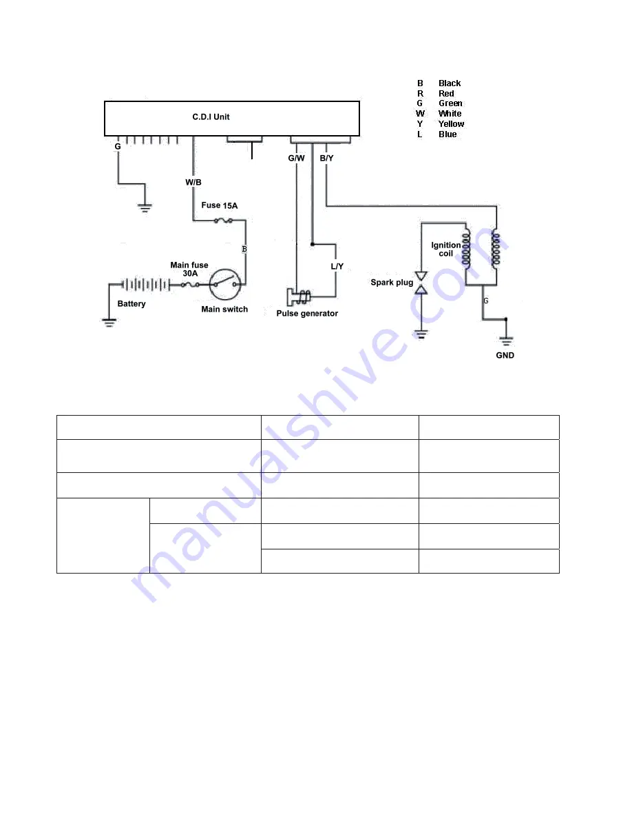
7. Ignition System
Ignition circuit diagram
C.D.I unit
Disconnect connectors of the C.D.I unit.
Check the following connectors as indicated in the table at the harness side.
Item
Points to check
Result
Main switch turn to
“ON”position
B ~ W/B
Battery voltage
Pulse generator
G/W ~ L/Y
50~170
Primary circuit
B/Y ~ GND
2.9±10%
B/Y ~ with no cap
15.0±10%
Ignition coil Secondary
circuit
B/Y ~ with cap
20.0
s
10%K
Summary of Contents for Patriot 430
Page 1: ...SERVICE MANUAL PATRIOT 430...
Page 4: ...3 SERIAL NUMBER Frame number Engine number Home page Contents...
Page 24: ...23...
Page 25: ...24...
Page 26: ...25...
Page 27: ...26...
Page 28: ...27 7 Lubrication Points...
Page 71: ...70 Muffler mounting bolt 12 N m Tighten the muffler bolts specified torque 29 N m...
Page 139: ...L CASE R CASE...
Page 148: ...Apply Loctite 510 Flange sealant to the mating surface of the left crankcase L CASE R CASE...
Page 161: ......
Page 162: ......
Page 235: ...1 Electrical Diagram 18 1...


