35
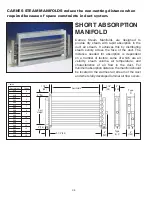
CARNES STEAM MANIFOLDS with strong galvanized flanged frames are factory
assembled to reduce installation costs.
LOCATION OF MANIFOLD
The manifold is usually located in the supply duct downstream of
the fan, heating coil, cooling coil, and/or filter. When installed in
packaged units, the manifold is to be mounted just downstream of
the fan discharge.
The non-wetting dimension is the distance necessary to prevent
condensation on any obstruction downstream from the manifold.
Condensation could occur on a cooling coil because of lower
temperatures. Steam plumes may be visible beyond the
non-wetting dimension and may moisten high efficiency filters.
Additional distance is required for installation upstream of high
efficiency filters.
Carnes humidifiers operate at 1/2 psi or less so there are
limitations on the length between the humidifier cabinet and the
steam manifold. The maximum distance depends on the static
pressure in the duct and is shown in
Table 6
.
MAXIMUM STEAM HOSE LENGTH
(Table 6)
Duct Static
0 1 2 3 4 5
Pressure
“wg”
Maximum Steam
40 35 30 25 15 10
Hose Length (Ft.)
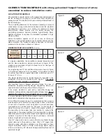
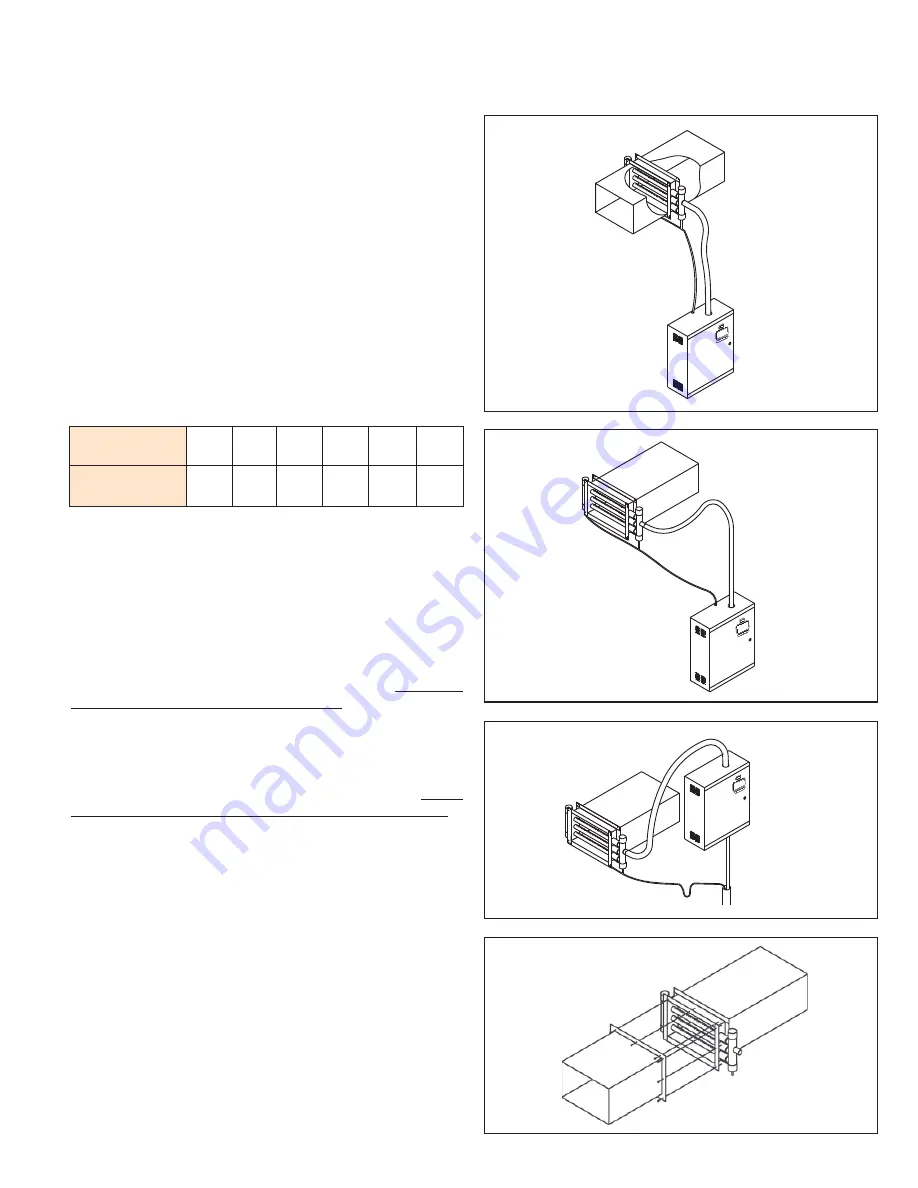
In a typical installation, the humidifier is located below the duct
and the steam manifold is installed as shown in
Figure R
. The
maximum recommended length of steam hose for this type of
installation is 12 feet.
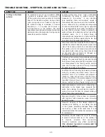
For lengths beyond 12 feet additional steps are shown in
Figure
S
. If sufficient headroom is not available, it is possible to install
the steam hose with an upward slope with a minimum rise of 2”
for every 12” of run.
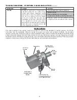
The steam manifold may be located below the humidifier if the
installation is made in accordance with
Figure T
. The steam
manifold cannot be installed in a vertical duct.
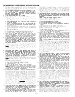
The manifold has an integral mounting flange for ease of
installation. Separate mounting flanges, supplied by others, are
needed to mate with the manifold.
Refer to Figure U
.
If the steam manifold is used with a humidifier having two
cylinders it will require two separate lengths of steam hose.
Do not
combine the outputs of two cylinders into one steam hose.
It is very important that both the steam hose and condensate
return line be installed so that sags are prevented.
If it is difficult to prevent sags, it is recommended that a copper
tube be used as a substitute. If a copper tube is used, a minimum
of one inch of insulation must be applied to prevent excessive
condensation and contact with the hot pipe. A short length of
steam hose must be used to connect the plastic cylinder in
the humidifier to the copper tube and another to connect the
copper tube to the steam manifold. It is very important to include
adequate space to move the steam hose far enough when replacing
cylinders. Any turns in the steam hose should have a minimum
radius of eight inches to prevent kinking.
Size 3/4” copper tube can be used with steam cylinders having
output rates up to 30 pounds per hour. Size 1-1/2” copper tube
should be used with steam cylinders over 30 pounds per hour.
Length restrictions shown in
Table 6
also apply where copper
tube is used and any 90° elbows add approximately three feet of
equivalent length.
Figure R
Figure S
Figure T
Figure U


