background image


ExRobotics B.V.  
ExR-2 Robot 
Operating Guide 

Document No.: 
20220412IP1 
Version No.: 2 

Owner: 
 
Ian Peerless 

Date: 
 
2022-04-30 

Page 28 of 39


This document is considered an uncontrolled copy when printed. Always ensure that you print and use a current version. 
Copyright 2022 ExRobotics B.V. 


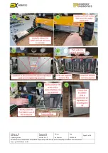
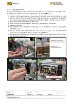
Reverse the above steps to replace the batteries and re-assemble the lid and panels. Ensure:  


Only batteries supplied by ExRobotics are used

. Any other batteries will invalidate the robot’s 

Ex certification. 


The foam strips around the inside of the battery enclosure remain secure. New strips 
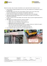
(supplied by ExRobotics) will be installed on the batteries (Picture 8). 


The thermal sensors between the batteries and their gap pads are not dislodged. 


The bolts connecting the battery leads to the terminals are torqued to 3.6 Nm with a 
calibrated torque wrench. 


Ty-raps are used to ensure the battery leads and other wires cannot be trapped between two 
metal parts. 


The screws for the battery pack lid are correctly installed: 

o


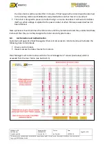
Tighten them in the sequence shown in Picture 5. 

o


Tighten each screw a little before moving to the next. 

o


Repeat this cycle until each screw is tight. 

o


Check that the lid is pressed securely onto the 

battery enclosure so that there’s a good 

seal. This is essential to the integrity of this Ex enclosure.  

o


Torque each screw to 7 Nm with a calibrated torque wrench. 


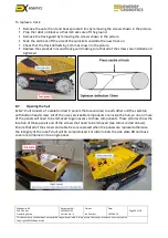
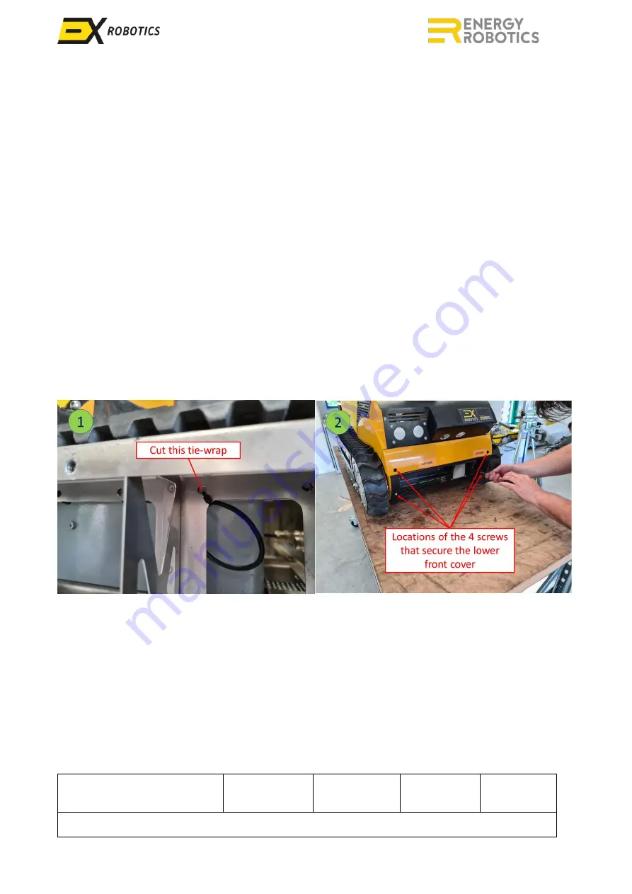
The microphone cable is looped and the Ty-rap replaced (Picture 1). 


Summary of Contents for ExR-2

Page 1: ...ExRobotics B V Delftechpark 26 2628 XH Delft The Netherlands sales exrobotics global ExR 2 Robot Operating Guide ...

Page 2: ... author Name Ian Peerless Job Title Director Signature Date Accountable Person who is accountable for the quality validity and timeliness of the document i e Process Owner Name Ian Peerless Job Title Director Signature Date Consulted on this document version Persons who have endorsed the document Names Stefan Kohlbrecher Jeroen Mostert Alberto Romay Dorian Scholz Ronald Schreurs Daan Hitzbleck Inf...

Page 3: ...d Always ensure that you print and use a current version Copyright 2022 ExRobotics B V Document Change Log Version Date of re issue Changes Made Page Author of Change 1 2022 04 12 First draft derived from Robot System Operating Guide 20190122IP1 Version 12 All Ian Peerless 2 2022 04 30 Included Energy Robotics comments and additional details about battery replacement Various Ian Peerless ...

Page 4: ...ditor 16 6 4 Mission Report 16 6 5 Engineer Screen 17 7 Autonomous Missions 17 7 1 Overview 17 7 2 Line Following Navigation 18 7 3 Tag Based Inspections 18 7 4 Teach and Repeat Navigation 19 7 5 Skills 23 7 6 Click and Inspect 23 8 Operating Robots 23 8 1 Operative Training 23 8 2 Authorisation and Authentication 24 8 3 Customer support 25 8 4 Software releases 25 8 5 Routine Maintenance 25 8 6 R...

Page 5: ...prised by the battery level reported by the cloud software 33 9 8 How do I refresh my control screen 33 9 9 Why does my robot drift to the left or right 33 9 10 Why have I experienced unexpected behaviour while operating a robot 33 9 11 How do I wash a contaminated robot 34 10 Robot and Docking Station Specifications 35 10 1 Environment 35 10 2 Terrain and Manoeuvrability 35 10 3 Availability 36 1...

Page 6: ... and docking stations The guides provide additional information about robot systems and their use The guides don t usually replicate important information that s in the instructions so it s essential that robot users read and understand the instructions If there s a conflict between the documents the instructions will always prevail This operating guide Describes each key part of the robot system ...

Page 7: ...when printed Always ensure that you print and use a current version Copyright 2022 ExRobotics B V 2 Robots ExR 2 robots are assembled from a number of modules mounted on a skeleton that is clad in sheet steel Many of these modules are optional The full range of modules is identified in these clad and unclad pictures More detailed robot specifications are included in Section 10 ...

Page 8: ...tations By default robots are controlled with a PC with a screen resolution of at least 1920 x 1080 and Google Chrome or Microsoft Edge Xbox gamepad for driving the robot Mouse or trackpad for operating the cursor on the PC s screen Should a customer prefer to control their robots with tablets without gamepads they should perform a risk assessment because there will be no physical emergency stop o...

Page 9: ...f the docking station the operative should stop driving forwards and switch off the motors by pressing the red button on the gamepad Once the induction charger is connected the Wireless Charger and Charging boxes on the cloud software will be checked Hovering the cursor over the charging box will reveal the charging current It takes approximately 8 hours to recharge a battery pack from 10 to 90 ch...

Page 10: ... 3 meters long If the robot is docked you should first switch off power to the induction charger When inserting the quick charge plug rotate the entire body clockwise before tightening the ring around its base You can check the status of the charging using the LEDs and instructions on the quick charger This video provides more detail https exrobotics global media uploads mp4 5 8 58_instruction how...

Page 11: ...conditions can hamper performance Condition Description Potential work arounds Drop offs Drop offs are more difficult to detect than obstacles because if the ground is very reflective for instance in heavy rain there might be false positives and steep downward ramps cannot be reliably distinguished from drop offs using LiDAR alone Drop offs are usually permanent features and it s very serious if t...

Page 12: ...ion module This is especially significant during sharp turns and for thin overhead items like cables Keep robot routes clear of such items Shiny and low reflection items The Ex enclosure of the LiDAR causes significant attenuation which means shiny and low reflective objects might be detectable only close to the robot Paint or cover these items Avoid leaving shiny temporary items on the robot s ro...

Page 13: ... are operated and data is collected using the cloud Access is granted as described in Section 8 2 Six types of screens are available as described below 6 1 Fleet Management and Fleet Status Fleet Management is the first screen that appears when users log on It allows them to connect to any robot to which they ve been granted access Scrolling down reveals more robots The Fleet Status screen see bel...

Page 14: ...ept button to capture the image Alternatively you can take a full size picture without selecting the POI icon Snapshots are displayed in the Media Log once they have been uploaded to the server this happens automatically after taking them and can be viewed in large scale by clicking on them From there they can be saved to the local machine by right clicking the full sized picture and selecting Sav...

Page 15: ... won t sleep If it s unticked the robot will save 4G costs and battery power by sleeping whether or not it s docked Select a mission using the drop down box To launch the mission click on the Play button to the left of the mission drop down box to cancel the mission press the button again Missions will usually be started when the robot is in a docking station However it s also possible to launch l...

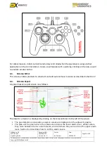
Page 16: ... the navigation menu to the top left of the screen They can report issues to our engineers using the Feedback option in the user menu to the top right of the screen The Gamepad controls are illustrated below The green A button activates remote control by enabling the gamepad and drive motors It also de activates the emergency stop button see below When this is done it will typically take 30 second...

Page 17: ...cking on the pop up will re enable remote control 6 3 Mission Editor This screen enables planners to construct and edit autonomous missions as described in Section 7 6 4 Mission Report A typical mission report screen is as follows The data for a mission is displayed by clicking on the relevant block to the left of the screen The gas detector and acoustic analyser values are displayed on the adjace...

Page 18: ... pumps To target the POI the robot will usually need to change its azimuth rotate and in some cases will require a camera to lift its field of view elevate There can be more than one action at a POI Waypoints are 2D locations from which POIs are observed There can be multiple POIs at a waypoint In Line following navigation waypoints are defined by an array of chili tags There can be multiple waypo...

Page 19: ...0 robot rotates 180 degrees or 09 00 robot rotates 90 degrees counter clockwise From the Mission Editor screen select action Undocking Select the Exit Direction e g 09 00 Write a name in Select Action Name e g Undock Click Save For waypoints that are used as junctions where a robot selects between alternative routes From the Mission Editor screen select action Junction Select Exit Direction e g 06...

Page 20: ...om 4 for other waypoints 11 Finally click on the yellow Disk icon on the bottom right to save the mission All inspection actions e g Photo can also be defined and executed at junction waypoints For this you just need to add the actions that you require to the waypoint number as described previously and then add a Junction action to the same waypoint number Actions are listed by waypoint in the rig...

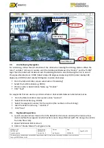
Page 21: ...2 04 30 Page 20 of 39 This document is considered an uncontrolled copy when printed Always ensure that you print and use a current version Copyright 2022 ExRobotics B V 3 Click on yellow button Create Mission 4 Give a unique name and click Create 5 Add a new route by clicking on the grey button Add new route ...

Page 22: ... least 1m away from the docking station see image below 9 Turn in the direction you want to drive 10 Start navigating through the environment until you reach your first waypoint 11 You have different options photo video audio or waypoint 12 For photos and videos you may need to rotate the inspection module panning as described in Section 5 2 Once the POI is in the Field of View FoV you can take a ...

Page 23: ...ion Copyright 2022 ExRobotics B V 14 Actions will appear in a list below 15 Repeat these steps until you ve covered all of the POIs 16 Drive back to the docking station and stop 1m before the docking station see image 17 Click on the red button to stop recording the mission 18 Accept the confirmation dialog 19 Your mission is now saved 20 Drive over the docking station to charge the robot and wait...

Page 24: ...urroundings using all cameras before enabling the drive motors When starting a mission and reversing away from the docking station the driver should use the inspection module panning to look behind the robot and check for obstructions Test the controls after leaving the docking station and before commencing a mission Approach hazards such as ledges sumps ramps overhead obstructions and the docking...

Page 25: ...afe driving so in some situations it will auto immobilise itself e g when voltage is applied to the power socket or when the keep awake box has not been checked New operatives should not drive the robot alone until they ve demonstrated they understand these items and that they can safely navigate the robot around typical routes 8 2 Authorisation and Authentication Customers will appoint a Fleet Ma...

Page 26: ...ftware is updated the account manager will Agree with the customer whether the release is applicable and any charges that will apply Decide when the release can best be installed to minimise disruption to the customer 8 5 Routine Maintenance When the opportunity arises the customer will perform simple routine maintenance The camera and light windows will be cleaned with a damp soft cloth The charg...

Page 27: ...that the track deflects by 12mm as shown in the picture Replace the sprocket rims and track guard making sure that all of the screws are installed and tightened 8 7 Opening the hull ExR 2 s hull consists of a skeleton clad in panels that are secured to each other and the skeleton with button head screws All of the user serviceable components are inside the hull so one or more of the panels will ne...

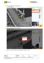
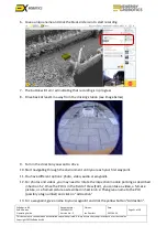
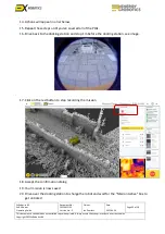
Page 28: ...e the extra cable that s required when removing the robot s lower front cover Remove the 4 screws that secure the robot s lower front cover carefully pull out from the hull spare cable for the microphone and charger and put the cover to one side Pictures 2 and 3 Remove the 2 screws that secure the robot s upper front cover and put the cover to one side Picture 4 These are dome head screws unlike t...

Page 29: ...n the batteries Picture 8 The thermal sensors between the batteries and their gap pads are not dislodged The bolts connecting the battery leads to the terminals are torqued to 3 6 Nm with a calibrated torque wrench Ty raps are used to ensure the battery leads and other wires cannot be trapped between two metal parts The screws for the battery pack lid are correctly installed o Tighten them in the ...

Page 30: ...Guide Document No 20220412IP1 Version No 2 Owner Ian Peerless Date 2022 04 30 Page 29 of 39 This document is considered an uncontrolled copy when printed Always ensure that you print and use a current version Copyright 2022 ExRobotics B V ...

Page 31: ...ack Picture 1 below Gently pull the enclosure front off the back taking great care not to damage the flame paths Picture 2 If a flame path is scratched or dented the robot s Ex certification will be invalid Pull out the status indicator board Picture 3 Press the front of the existing SIM Picture 4 It will spring out of its holder Insert the new SIM Re install the status indicator board aligning it...

Page 32: ... that you print and use a current version Copyright 2022 ExRobotics B V 8 11 Security Robots are fitted with security features People cannot connect to the robot unless they have the necessary authentication The 4G network provider will be able to locate the robot when it s powered on Communications are protected by sophisticated IT security Your account manager can provide more information if req...

Page 33: ...ustomer firewall has blocked access The connection to the robot consists of two types one for the control commands via HTTPS over TCP and one for very low latency video signals via WebRTC over UDP To be able to control the robot from a computer within corporate networks both connection types need to be allowed by both the corporate and the computer firewall Your account manager can advise you of t...

Page 34: ... low This protects the batteries which should be undamaged unless the robot isn t connected to a charger within 2 weeks Never leave the quick charger connected to the robot but not to a power supply This will reduce a full battery s life to 6 weeks even if the robot is switched off Sometimes the 3 batteries in a robot s battery pack become unbalanced and battery life declines significantly They ma...

Page 35: ... file and an explanation to our engineers 9 11 How do I wash a contaminated robot You can use a water jet spray to wash the robot if for example it may have been exposed to hazardous chemicals However do not point the jet directly at Camera and light module windows The microphone opening in the robot s front panel The on off switch or emergency stop Any exposed hexagonal plugs including those on t...

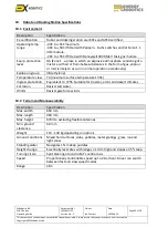
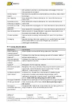
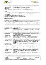
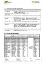
Page 36: ...ammable substances in the form of gas vapour or mist is likely to occur in normal operation occasionally Explosion group IIB ethylene Temperature class T4 maximum surface temperature 135C Ingress protection Equivalent to IP55 Suitable for tropical arctic and desert climates Corrosion Resists salt water Winds Resists gale force winds 10 2 Terrain and Manoeuvrability Description Specification Max wi...

Page 37: ...es a forward facing 18 MP digital video camera 690 Lm LED that pans 180 Live video transmission to web browser interface Zoomed still images and video recordings can be taken and downloaded from the web browser interface Drive camera module Forwards downwards facing 1 2 MP digital video camera 690 Lm LED with the same functionality as the inspection module panning optical Microphone Mono microphon...

Page 38: ...ase 800 will be deducted from next order if flight case is returned undamaged to ExRobotics 10 5 Sensing Audio Options Description Specification Extra inspection module optical Fixed inspection camera LED facing upwards or forwards Inspection module thermal FLIR Boson thermal IR camera facing upwards or forwards With or without optical camera Panning optical thermal inspection module FLIR Boson th...

Page 39: ...ad of 4G LTE Customer to provide WiFi network with comprehensive coverage latency of less than 250 ms an upload bandwidth of at least 5 Mbit s 4G LTE WiFi Transparent switching between 4G LTE WiFi Not available if GPS is installed COMING SOON GPS antenna Robot localises itself using GPS COMING SOON Communications module Contains NVIDIA Xavier processor robot status indicator short range WiFi for c...

Page 40: ...day storage PDF reports PDF copy of mission asset analysis reports E Mailed at the end of each mission Basic API For transferring data from and instructions to robot Details available on request 10 000 queries month robot 10 simultaneous subscriptions robot Extended API As for basic API but with 100 000 queries month robot 100 simultaneous subscriptions robot Skill store We can offer a wide range ...

Reviews: