


Ver: IC13-EN-10567
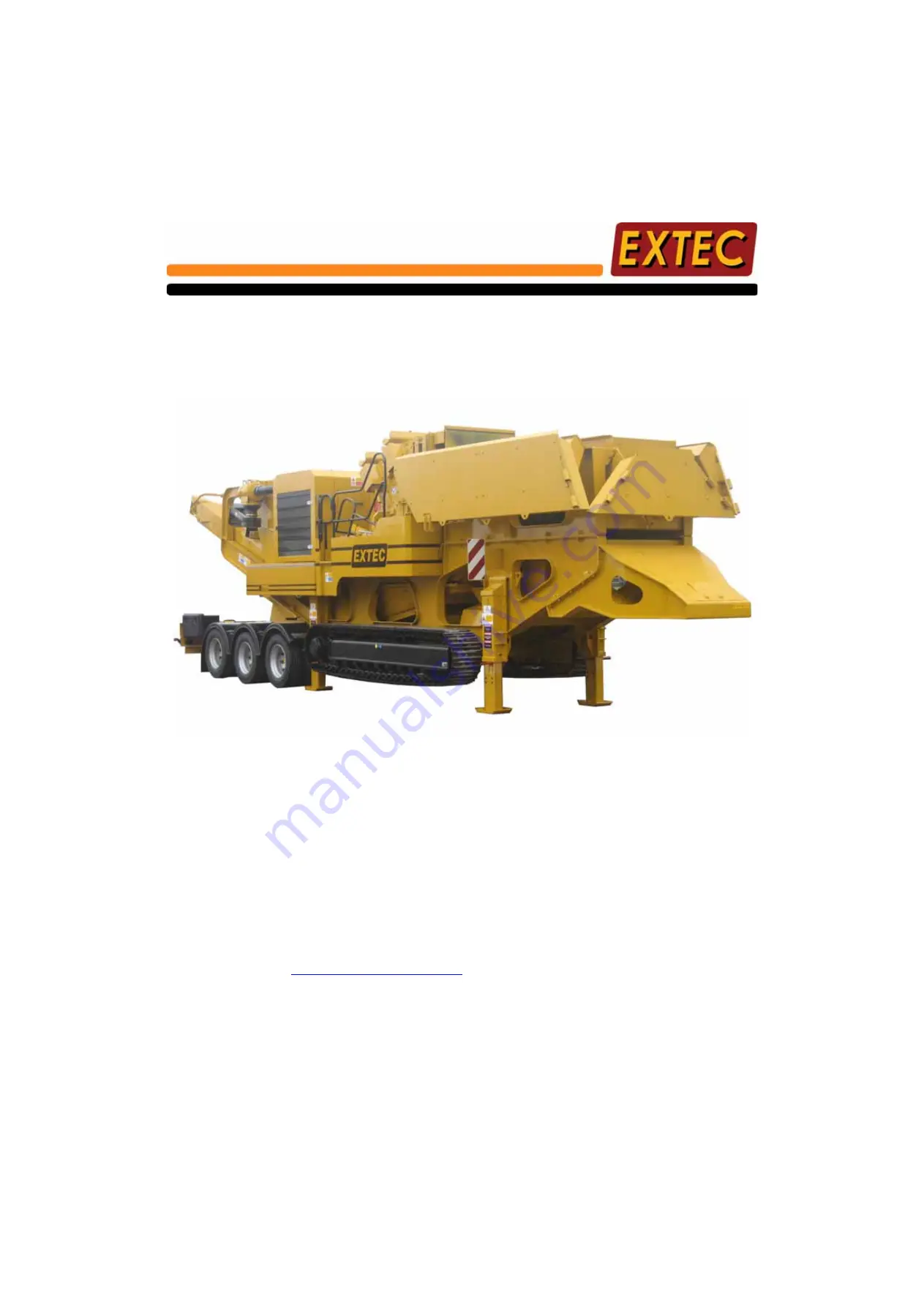
Operating and Maintenance Manual
19 June 2007
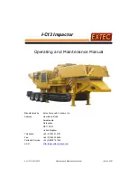
I-C13 Impactor
Operating and Maintenance Manual
Manufactured by:
Extec Screens & Crushers Ltd
Address:
Hearthcote Road
Swadlincote
Derbyshire
DE11 9DU
United Kingdom
Telephone:
+44 (0)1283 212121
Fax:
+44 (0)1283 226465
Parts and Service:
+44 (0)8000 181945
www:
Summary of Contents for I-C13 Impactor
Page 10: ...Page x Contents Ver IC13 EN 10567 I C13 Impactor...
Page 13: ...Ver IC13 EN 10567 Safety Instructions Page 3 I C13 Impactor...
Page 14: ...Page 4 Safety Instructions Ver IC13 EN 10567 I C13 Impactor...
Page 26: ...Page 16 Safety Instructions Ver IC13 EN 10567 I C13 Impactor Intentionally left blank...
Page 34: ......
Page 80: ...Page 70 Trouble Shooting Guide Ver IC13 EN 10567 I C13 Impactor Intentionally left blank...
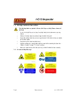
Page 185: ...Ver IC13 EN 10567 Stickers English Page 175 I C13 Impactor 11 12 13 14 15 16 17 18...
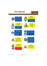
Page 186: ...Page 176 Stickers English Ver IC13 EN 10567 I C13 Impactor 19 20 21 22 23 24 25 26 27 28...
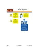
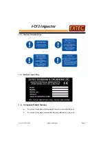
Page 187: ...Ver IC13 EN 10567 Stickers English Page 177 I C13 Impactor 29 30 31 32 33 34 35 36...
Page 195: ...Ver IC13 EN 10567 Water Pump Optional Page 185 I C13 Impactor Intentionally left blank...
Page 196: ...Page 186 Water Pump Optional Ver IC13 EN 10567 I C13 Impactor...
Page 198: ...Page 188 Ver IC13 EN 10567 I C13 Impactor Figure B 1 CONTROL CONNECTOR...
Page 199: ...Ver IC13 EN 10567 Page 189 I C13 Impactor Figure B 2 CONTROLLER CONNECTOR...
Page 200: ...Page 190 Ver IC13 EN 10567 I C13 Impactor Figure B 3 ENGINE SCHEMATIC...
Page 201: ...Ver IC13 EN 10567 Page 191 I C13 Impactor Figure B 4 RECEIVER AND LOOM...
Page 202: ...Page 192 Ver IC13 EN 10567 I C13 Impactor Figure B 5 SOLENOID CONTROL PANEL...
Page 203: ...Ver IC13 EN 10567 Page 193 I C13 Impactor Figure B 6 ELECTRONIC PANEL...
Page 204: ...Page 194 Ver IC13 EN 10567 I C13 Impactor Figure B 7 AUXILARY LOOMS...
Page 206: ...Page 196 Ver IC13 EN 10567 I C13 Impactor Figure B 9 RECIRC REL TRACK VALVE LOOM...
Page 208: ...Ver IC13 EN 10134 Page 198 I C13 Impactor Intentionally left blank...
Page 210: ...Page 200 Ver IC13 EN 10567 I C13 Impactor Intentionally left blank...
Page 218: ...Page 210 Ver IC13 EN 10567 I C13 Impactor Intentionally left blank...
Page 219: ...Ver IC13 EN 10567 Page 211 I C13 Impactor...
Page 220: ...Page 212 Ver IC13 EN 10567 I C13 Impactor...
Page 221: ...Ver IC13 EN 10567 Page 213 I C13 Impactor...
Page 222: ...Page 214 Ver IC13 EN 10567 I C13 Impactor...
Page 223: ...Ver IC13 EN 10567 Page 215 I C13 Impactor...
Page 224: ...Page 216 Ver IC13 EN 10567 I C13 Impactor...
Page 225: ...Ver IC13 EN 10567 Page 217 I C13 Impactor...
Page 226: ...Page 218 Ver IC13 EN 10567 I C13 Impactor...
Page 227: ...Ver IC13 EN 10567 Page 219 I C13 Impactor...
Page 228: ...Page 220 Ver IC13 EN 10567 I C13 Impactor...
Page 229: ...Ver IC13 EN 10567 Page 221 I C13 Impactor...
Page 230: ...Page 222 Ver IC13 EN 10567 I C13 Impactor...
Page 231: ...Ver IC13 EN 10567 Page 223 I C13 Impactor...
Page 232: ...Page 224 Ver IC13 EN 10567 I C13 Impactor...
Page 233: ...Ver IC13 EN 10567 Page 225 I C13 Impactor...
Page 234: ...Page 226 Ver IC13 EN 10567 I C13 Impactor...
Page 235: ...Ver IC13 EN 10567 Page 227 I C13 Impactor...
Page 236: ...Page 228 Ver IC13 EN 10567 I C13 Impactor...
Page 237: ...Ver IC13 EN 10567 Page 229 I C13 Impactor...
Page 238: ...Page 230 Ver IC13 EN 10567 I C13 Impactor...
Page 239: ...Ver IC13 EN 10567 Page 231 I C13 Impactor...
Page 240: ...Page 232 Ver IC13 EN 10567 I C13 Impactor...
Page 241: ...Ver IC13 EN 10567 Page 233 I C13 Impactor...
Page 242: ...Page 234 Ver IC13 EN 10567 I C13 Impactor...
Page 243: ...Ver IC13 EN 10567 Page 235 I C13 Impactor...
Page 244: ...Page 236 Ver IC13 EN 10567 I C13 Impactor...
Page 245: ...Ver IC13 EN 10567 Page 237 I C13 Impactor...
Page 246: ...Page 238 Ver IC13 EN 10567 I C13 Impactor...
Page 247: ...Ver IC13 EN 10567 Page 239 I C13 Impactor...
Page 248: ...Page 240 Ver IC13 EN 10567 I C13 Impactor...
Page 249: ...Ver IC13 EN 10567 Page 241 I C13 Impactor...
Page 250: ...Page 242 Ver IC13 EN 10567 I C13 Impactor...
Page 251: ...Ver IC13 EN 10567 Page 243 I C13 Impactor...
Page 252: ...Page 244 Ver IC13 EN 10567 I C13 Impactor...
Page 253: ...Ver IC13 EN 10567 Page 245 I C13 Impactor...
Page 254: ...Page 246 Ver IC13 EN 10567 I C13 Impactor...
Page 255: ...Ver IC13 EN 10567 Page 247 I C13 Impactor...
Page 256: ...Page 248 Ver IC13 EN 10567 I C13 Impactor...
Page 257: ...Ver IC13 EN 10567 Page 249 I C13 Impactor...
Page 258: ...Page 250 Ver IC13 EN 10567 I C13 Impactor...
Page 259: ...Ver IC13 EN 10567 Page 251 I C13 Impactor...
Page 260: ...Page 252 Ver IC13 EN 10567 I C13 Impactor...
Page 261: ...Ver IC13 EN 10567 Page 253 I C13 Impactor...
Page 262: ...Page 254 Ver IC13 EN 10567 I C13 Impactor...
Page 263: ...Ver IC13 EN 10567 Page 255 I C13 Impactor...
Page 264: ...Page 256 Ver IC13 EN 10567 I C13 Impactor...
Page 265: ...Ver IC13 EN 10567 Page 257 I C13 Impactor...
Page 266: ...Page 258 Ver IC13 EN 10567 I C13 Impactor...
Page 267: ...Ver IC13 EN 10567 Page 259 I C13 Impactor...
Page 268: ...Page 260 Ver IC13 EN 10567 I C13 Impactor...
Page 269: ...Ver IC13 EN 10567 Page 261 I C13 Impactor...
Page 270: ...Page 262 Ver IC13 EN 10567 I C13 Impactor...
Page 271: ...Ver IC13 EN 10567 Page 263 I C13 Impactor...
Page 272: ...Page 264 Ver IC13 EN 10567 I C13 Impactor...
Page 273: ...Ver IC13 EN 10567 Page 265 I C13 Impactor...
Page 274: ...Page 266 Ver IC13 EN 10567 I C13 Impactor...
Page 275: ...Ver IC13 EN 10567 Page 267 I C13 Impactor...
Page 276: ...Page 268 Ver IC13 EN 10567 I C13 Impactor...
Page 277: ...Ver IC13 EN 10567 Page 269 I C13 Impactor...
Page 278: ...Page 270 Ver IC13 EN 10567 I C13 Impactor...
Page 279: ...Ver IC13 EN 10567 Page 271 I C13 Impactor...
Page 280: ...Page 272 Ver IC13 EN 10567 I C13 Impactor...
Page 281: ...Ver IC13 EN 10567 Page 273 I C13 Impactor...
Page 282: ...Page 274 Ver IC13 EN 10567 I C13 Impactor...
Page 283: ...Ver IC13 EN 10567 Page 275 I C13 Impactor...
Page 284: ...Page 276 Ver IC13 EN 10567 I C13 Impactor...
Page 285: ...Ver IC13 EN 10567 Page 277 I C13 Impactor...
Page 286: ...Page 278 Ver IC13 EN 10567 I C13 Impactor...
Page 287: ...Ver IC13 EN 10567 Page 279 I C13 Impactor...
Page 288: ...Page 280 Ver IC13 EN 10567 I C13 Impactor...
Page 289: ...Ver IC13 EN 10567 Page 281 I C13 Impactor...
Page 290: ...Page 282 Ver IC13 EN 10567 I C13 Impactor...
Page 292: ...Page 284 Ver IC13 EN 10567 I C13 Impactor Intentionally left blank...


