background image

380820-en-GB_V1.5   3/15 

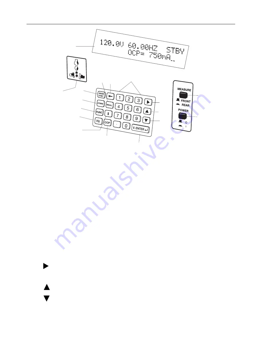
Front Panel Description 


1. 

Front Output Socket: 

Use the following formula to determine the continuous use capability of 

the output: Time (t) = 100 / Watt (w). For example, 100W power can be continuously output for 
1 minute and 50W could be continuously output for 2 minutes. Switch off the tester for 20 
minutes (for ventilation) between output sessions. 

2. 

OPER/STBY: 

Press to enable/disable the output. When the unit is in STBY mode, the output is 

0 volts. When the unit is in OPER mode, the power will not output until the voltage level is 
stable; this is to prevent damage to connected devices from unstable voltage. 

3. 

 Backspace: 

If a typing error is made, use the 


button to clear the digit to the left. 

4. 

LCD: 

Liquid Crystal Display 

5. 

RECALL: 

Recalls stored voltage and frequency values (there are 99 sets of preset values in 

the memory). The currently selected voltage and frequency values will clear when the RECALL 
button is pressed. Type


a memory location number (1 to 99) and then press the V.ENTER 

button to confirm. If no data is stored in a particular location, the LCD will display “BLANK 
number” (e.g. “BLANK 33”). Use the 

STORE

 button to save a voltage/frequency value to a 

memory location. 

6. 

Numeric Keypad: 

The numeric keypad is a user programming interface. 

7. 

     :  

Moves the cursor to the next digit. 

8. 

OUTPUT FRONT/REAR: 

Selects the output. Press downward to display the Rear Output 

status. Press upward to display the Front Output status. 

9. 

      :  

Increases a value. 

10. 

      :  

Decrease a value. 

11. 

POWER ON/OFF: 

Press to switch the supply ON or OFF. 

12. 

V.ENTER: 

Press to confirm a program entry. 

2

1

3

4

5

6

7

8

9

10

11

13

14

15

16

17

12

Summary of Contents for 380820

Page 1: ...User s Guide Universal AC Power Source AC Power Analyzer Model 380820...

Page 2: ...ly to a mains outlet with an earth ground connection Do not place the equipment on damp or wet surfaces Do not subject the equipment to direct sunlight or extreme temperatures Do not subject the equip...

Page 3: ...r loss of life and prevent damage to this product Earth Ground Terminal This unit has been tested and meets or exceeds the following standards 1 EN61326 1 2006 CISPR11 IEC EN 61000 3 2 2006 IEC EN 610...

Page 4: ...ft 4 LCD Liquid Crystal Display 5 RECALL Recalls stored voltage and frequency values there are 99 sets of preset values in the memory The currently selected voltage and frequency values will clear whe...

Page 5: ...s to save the currently programmed voltage and frequency to one of the memory locations 1 to 99 and press V ENTER to confirm The currently selected voltage and frequency will be stored in the selected...

Page 6: ...ic Test Setup Diagram Connect the Unit Under Test to the 380820 Front and Rear Output Select When the unit is switched ON use the OUTPUT button to select the display for the Front or Rear output data...

Page 7: ...t is 0V however the output terminals are still physically connected to the internal circuit Frequency Output Front Output Rear Measurement 1 Type the desired frequency value and then press the Hz butt...

Page 8: ...t offers 99 memory locations To Store 1 Ensure that the desired voltage and frequency values are correctly set 2 Press the STORE button verify STORE _ appears on display 3 Assign a memory location num...

Page 9: ...press the button 2 When the unit is in OPER Output Mode changing the OCP value or the Voltage value will switch the mode from OPER to STBY standby Therefore pay careful attention to this operation 3 I...

Page 10: ...the FUNC button is pressed the LCD will display Voltage THD and harmonics n 1 50 Use the buttons to select the harmonics to be displayed 3 When the FUNC button is pressed again the LCD will display t...

Page 11: ...the output will be placed in STANDBY mode and the LCD will display OVERHEATED A displayed timer indicates the remaining cooling time that must elapse before the unit can be switched ON again When the...

Page 12: ...2 minutes if the output is less than 100VA If the output is less than 25VA then the output can run continuously Rear Panel Specifications Input power is looped through to the REAR output Max 2000VA 2...

Page 13: ...ity 85 RH Operation Temperature 4C to 60C 40 F to 140 F Accessories Power cord Software CD ROM RS232C to USB cable Dimensions 260mm x 151mm x 305 mm 10 2 x 5 9 x 12 0 Weight 9 9 kg s 21 8 lb Copyright...

Reviews: