42560 V5.0 8/08
3
Descriptions
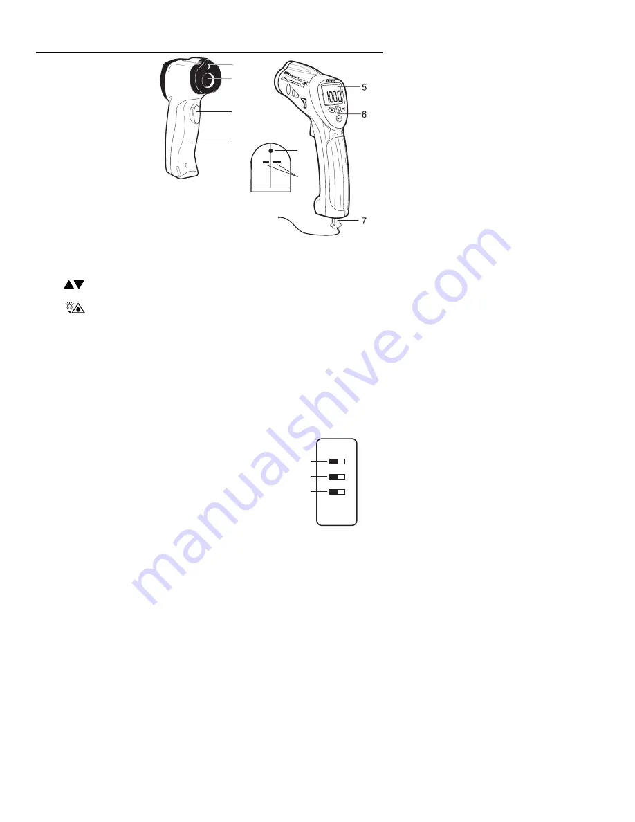
Meter Description
1. Laser
pointer
2. IR
sensor
3. Measurement
trigger
4. Battery
compartment
5. LCD
display
6. Function
buttons*
7. Thermocouple
8. Optical
interface
(meter bottom)
9.
Thermocouple input jacks (meter bottom)
*Function Buttons
•
MODE
: Select from 9 modes of operation explained in detail in this user guide.
•
Arrows
: For setting the emissivity, high/low alarm limits, and for scrolling
through the 20 internal memory locations
•
Backlight / Laser Pointer
: For turning the LCD backlight and the Laser pointer
ON/OFF while taking measurements
•
USB
: For turning the wireless PC communications ON/OFF
•
SET
: For storing a reading to one of the 20 internal memories.
•
AT
E
: Used during the Automatic Emissivity Adjustment procedure.
Note: The function button explanations above are simple overviews. For precise
instructions, please read the entire User Guide.
Internal Switches (inside battery compartment)
1.
Temperature units (
o
C or
o
F) switch (
o
C is the left position)
2.
Test lock ON / OFF switch (OFF is the left position)
3.
Alarm ON / OFF switch (OFF is the left position)
1
2
3
4
1
2
3
8
9

