background image

42560  V5.0  8/08 

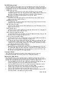
The MODE button options 

The MODE button is used to select from a list of available meter functions. The selected 
function is displayed on the bottom line of the LCD. Each function is listed below along with 
a detailed account of its use. Press the MODE button to step from one function to the next. 

EMS 

(Emissivity Value)


To change the emissivity value, use the UP and DOWN arrows (the available 
emissivity range is 0.10 to 1.00). The current emissivity setting is always shown at the 
top of the LCD display. A setting of 0.95 covers about 90% of all applications. 
Emissivity is discussed in a dedicated section of this User Guide. 

MAX 

(Maximum function) 

In the MAX mode, the highest reading encountered during a single measurement 
scan is displayed next to the MAX icon. 

MIN

 (Minimum function) 

In the MIN mode, the lowest reading encountered during a single measurement scan 
is displayed next to the MIN icon. 

DIF

 (Max minus Min value) 

In the DIF mode, the MAX less the MIN is displayed next to the DIF display icon for a 
single measurement scan. 

AVG

 (Average value) 

In the AVG mode, all of the readings in a single measurement scan are averaged and 
the result is displayed next to the AVG icon. 

HAL

 (High Alarm temperature setting) 

The temperature that, when exceeded, causes the audible/visual alarm to trigger. Use 
the arrow buttons to change the high alarm limit. 

LAL

 (Low Alarm temperature setting) 

The temperature that, when exceeded high to low, causes the audible/visual alarm to 
trigger. Use the arrow buttons to change the low alarm limit. 

T k

 (Type-K contact thermocouple sensor function) the temperature reading of the Type-

K contact probe is shown next to the ‘T k’ icon display. If the sensor is not correctly 
inserted to the meter the display will show ‘

OL

‘. The supplied thermocouple is rated 

for a maximum temperature of 482

o

F (250

o

C). 

LOG 1 through 20

 (20 reading internal datalogger) 

Repeatedly press the MODE button unit the LOG icon is displayed on the LCD. Pull 
the measurement trigger to take a reading and then press the SET button to store the 
reading to the location represented by the number shown next to the LOG icon. Use 
the arrow keys to navigate the 20 storage locations. 

Over-range Indicator 

If the temperature measurement exceeds the specified temperature range, the 
thermometer will display 

OL

 (overload) in place of a temperature reading.


High and Low Alarm Feature 

The Model 42560 has an alarm feature whereas a High Alarm setting and a Low Alarm 
setting can be programmed by the user. When either Alarm point is reached the meter will 
alert the user via an audible beep and LCD display icon. Follow the steps below: 

1. 

Press the MODE button until the HAL (High Alarm) parameter is displayed. Use the 
UP and DOWN arrow keys to set the desired High Alarm setting. 

2. 

Press the MODE button until the LAL (Low Alarm) parameter is displayed. Use the 
UP and DOWN arrow keys to set the desired Low Alarm setting. 

3. 

When an alarm limit is reached, the audible alarm will sound and the display icon 
HIGH or LOW will appear in the lower right hand corner of the LCD. 

4. 

Note that if the bottom DIP switch (located in the battery compartment) is set to OFF 
(left switch position), the audible alarm will be disabled. 

Summary of Contents for 42560

Page 1: ...User Guide InfraRed IR Thermometer with Wireless Datalogger Type K input Laser Pointer MODEL 42560 ...

Page 2: ...ars from date of shipment a six month limited warranty applies on sensors and cables If it should become necessary to return the instrument for service during or beyond the warranty period contact the Customer Service Department at 781 890 7440 ext 210 for authorization or visit our website at www extech com click on Contact Extech and go to Service Department to request an RA number A Return Auth...

Page 3: ...locations Backlight Laser Pointer For turning the LCD backlight and the Laser pointer ON OFF while taking measurements USB For turning the wireless PC communications ON OFF SET For storing a reading to one of the 20 internal memories ATE Used during the Automatic Emissivity Adjustment procedure Note The function button explanations above are simple overviews For precise instructions please read th...

Page 4: ... MODE button selection for example if Type K is selected Tk the thermocouple temperature reading will display here Transmitter Base Description 1 PC Interface activation button 2 PC communication status LED 3 Analog output jack 1mV per ºF for use with supplied 3 5mm to banana lead cable 4 Tripod Mount 5 12V DC 117VAC adaptor jack 6 Optical interface USB Receiver Module Description 1 Receiver modul...

Page 5: ... left switch position is ºC and the right position is ºF Backlight Laser Pointer 1 While pulling the Trigger push the backlight laser button to turn on the backlight 2 Press it again to turn on the laser pointer When the laser is ON the laser icon will appear in the LCD 3 Press again to turn the backlight off 4 Press one more time to turn the laser off Type K contact Measurements 1 Plug the Type K...

Page 6: ...uttons to change the low alarm limit T k Type K contact thermocouple sensor function the temperature reading of the Type K contact probe is shown next to the T k icon display If the sensor is not correctly inserted to the meter the display will show OL The supplied thermocouple is rated for a maximum temperature of 482 o F 250 o C LOG 1 through 20 20 reading internal datalogger Repeatedly press th...

Page 7: ...nt temperature However it can take up to 30 minutes for the meter to adjust to extremely wide changes 7 To find a hot spot aim the meter outside the area of interest then scan across in an up and down motion until the hot spot is located Field of View As the distance from the object increases the spot size of the area measured becomes larger The meter s field of view is 30 1 in other words if the ...

Page 8: ... 0 95 Water 0 92 to 0 96 Lacquer matt 0 97 Ice 0 96 to 0 98 Rubber black 0 94 Snow 0 83 Plastic 0 85 to 0 95 Glass 0 90 to 0 95 Timber 0 90 Ceramic 0 90 to 0 94 Paper 0 70 to 0 94 Marble 0 94 Chromium Oxides 0 81 Plaster 0 80 to 0 90 Copper Oxides 0 78 Mortar 0 89 to 0 91 Iron Oxides 0 78 to 0 82 Brick 0 93 to 0 96 Textiles 0 90 Automatic Emissivity Adjustment The 42560 has the ability to automati...

Page 9: ... the supplied software program The Main software screen is reproduced below for preview reference 1 Control buttons Save Open Print Select Com On Off Undo Zoom Clear Screen Clear All Help 2 Emissivity setting 3 MODE button selection 4 TIME sample rate UNLOCK LOCK Status of test lock dip switch RANGE Temperature range of meter UNIT Temperature unit of measure 5 Data graph display area 6 High and Lo...

Page 10: ... pursuant to part 15 of the FCC Rules These limits are designed to provide reasonable protection against harmful interference in a residential installation This equipment generates uses and can radiate radio frequency energy and if not installed and used in accordance with the instructions may cause harmful interference to radio communications However there is no guarantee that interference will n...

Page 11: ...lution 58 0 to 1999 9 o F 50 0 to 1370 0 o C 2000 F to 2498 F 0 1 o 1 Accuracy 1 5 of rdg 5ºF 3ºC from 58 to 1832ºF 50 to 1000ºC 1 5 of rdg 3 6ºF 2ºC from 1832 to 2498ºF 1000 to 1370ºC Note Accuracy is specified for the following ambient temperature range 64 to 82ºF 18 to 28ºC The supplied thermocouple is rated for 482 o F 250 o C General Specifications Display Backlit LCD display with function in...

Page 12: ...down away from the trigger area The panel is hinged at the bottom and does not completely disconnect from the meter Replace the 9V battery and close the battery compartment cover Note that the dip switches for TEST LOCK ON OFF UNIT OF MEAUSURE C F selection and AUDIBLE ALARM ON OFF explained earlier in this User Guide are located in the battery compartment behind the battery Calibration and Repair...

Reviews: