DCP42-EU-EN V1.2 9/13
12
6.3 Upper Voltage and Current Limits
When the voltage or current at the output terminal exceeds the maximum allowable limits, the
output will automatically switch OFF. This additional protection feature is necessary for a power
supply with such a wide range of voltage and current capabilities.
To set the UVL:
1. To set the UVL: Press the SHIFT button and then press the Voltage control knob. The
voltmeter will show the current limit setting and the Ammeter will show Suul.
2. Turn the Voltage control knob to the desired limit value. Press SHIFT to confirm and to
return to normal operation.
3. To set the UCL, press SHIFT and then press the Current control knob. The Ammeter will
show the current limit setting and the Voltmeter will show SUCL.
4. Turn the Current control knob to the desired limit value. Press SHIFT to confirm and to
return to normal operation.
Note: The UVL and UCL settings default to the maximum output value.
6.4 Remote Sensing
Note: Observe warnings displayed by the Power Supply, an incorrect disconnection sequence
will damage the Power Supply
Warnings:
Never short the Remote Sensing Terminal and always disconnect the Remote Sensing
Terminal first.
6.4.1 Connection
1. First complete the power connections between power supply and equipment.
2. Check and ensure that the power connections are secure.
3. Make connections between Remote Sensing and equipment.
Warning!:
Never short the Remote Sensing Terminal and never connect the Remote Sensing
Terminal in reverse polarity
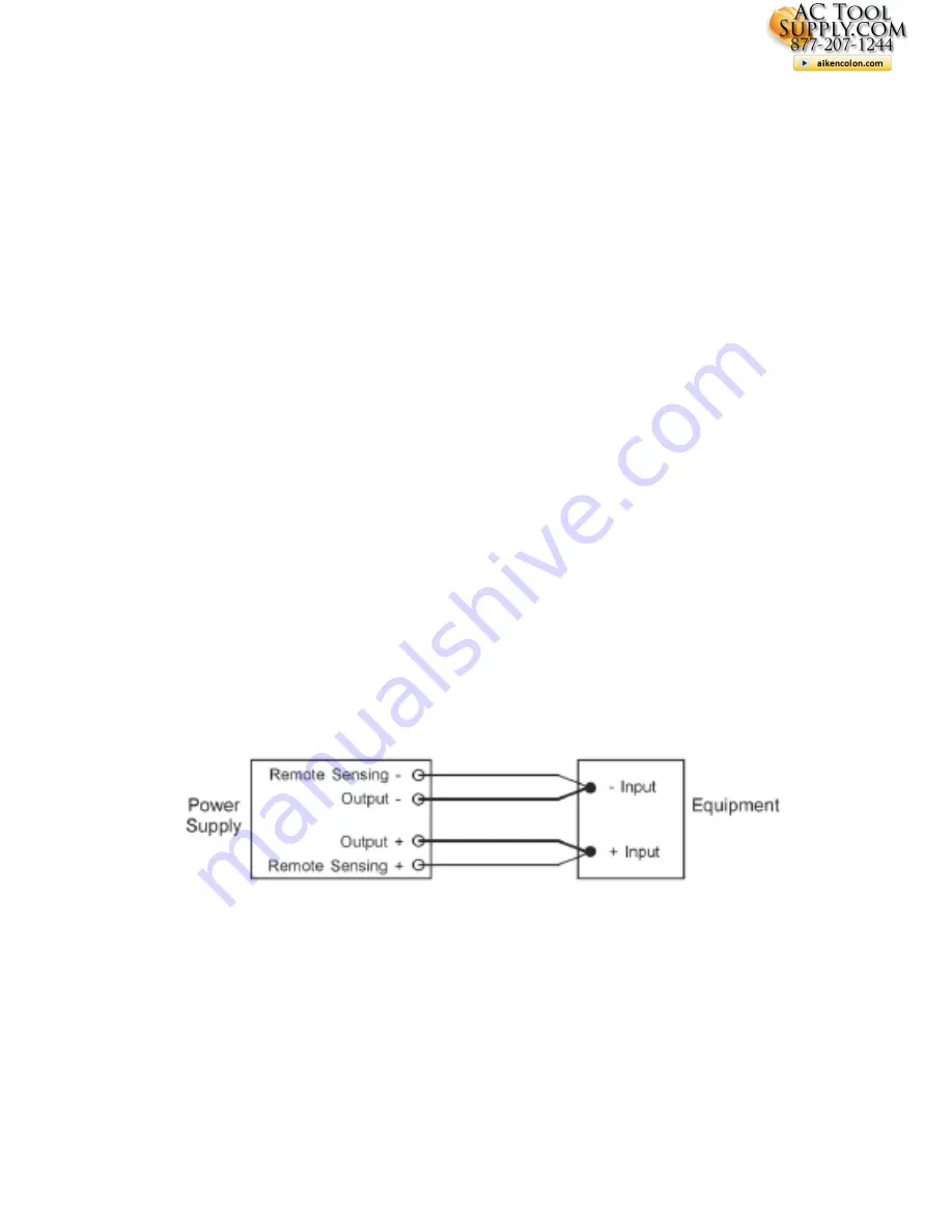
The diagram below shows the connections for Remote Sensing, Power output, and Equipment.
The remote sensing wire should be AT LEAST 22AWG wire size.
6.4.2 Disconnection
Warning! Incorrect disconnect sequences will damage the power supply
1. First disconnect the remote sensing connections.
2. Then disconnect the power connections between the power supply and equipment.
actoolsupply.com
actoolsupply.com


