MN10-en-GB_V1.3 09/16
5
AC VOLTAGE MEASUREMENTS
WARNING:
Risk of Electrocution. The probe tips may not be long enough to contact the live parts
inside some 240V outlets for appliances because the contacts are recessed deep in the outlets. As
a result, the reading may show 0 volts when the outlet actually has voltage on it. Make sure the
probe tips are touching the metal contacts inside the outlet before assuming that no voltage is
present.
CAUTION:
Do not measure AC voltages if a motor on the circuit is being switched ON or OFF.
Large voltage surges may occur that can damage the meter.
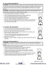
1. Set the function switch to the highest V AC position.
2. Insert the black test lead banana plug into the negative (COM) jack.
Insert red test lead banana plug into the positive (V) jack.
3. Touch the black test probe tip to the negative side of the circuit.
Touch the red test probe tip to the positive side of the circuit.
4. Read the voltage in the display. Reset the function switch to successively lower V
AC positions to obtain a higher resolution reading. The display will indicate the
proper decimal point and value.
DC CURRENT MEASUREMENTS
1. Insert the black test lead banana plug into the negative (COM) jack.
2. Set the function switch to the 200mA or 2000
A DC range position.
3. Insert the red test lead banana plug into the mA jack.
4. Remove power from the circuit under test, then open up the circuit at the point
where you wish to measure current.
5. Touch the black test probe tip to the negative side of the circuit.
Touch the red test probe tip to the positive side of the circuit.
6. Apply power to the circuit.
7. Read the current in the display. The display will indicate the proper decimal point
and value.
RESISTANCE MEASUREMENTS
WARNING:
To avoid electric shock, disconnect power to the unit under test and discharge all
capacitors before taking any resistance measurements. Remove the batteries and unplug the line
cords.
1. Set the function switch to the highest
Ω
position.
2. Insert the black test lead banana plug into the negative (COM) jack
Insert the red test lead banana plug into the positive jack.
3. Touch the test probe tips across the circuit or part under test. It is best to
disconnect one side of the part under test so the rest of the circuit will not
interfere with the resistance reading.
4. Read the resistance in the display and then set the function switch to the lowest
Ω
position that is greater than the actual or any anticipated resistance. The
display will indicate the proper decimal point and value.
www.
.com
information@itm.com
1.800.561.8187


