background image

MN15A    V1.1    02/09 

4

Operating Instructions 

WARNING

: Risk of electrocution. High-voltage circuits, both AC and DC, are very 

dangerous and should be measured with great care. 

NOTE

: On some low AC and DC voltage ranges, with the test leads not connected to a 

device, the display may show a random, changing reading. This is normal and is caused 
by the high-input sensitivity. The reading will stabilize and give a proper measurement 
when connected to a circuit. 


AC VOLTAGE MEASUREMENTS 

WARNING

:  Risk of Electrocution. The probe tips may not be long enough to contact the 

live parts inside some 240V outlets for appliances because the contacts are recessed deep 
in the outlets. As a result, the reading may show 0 volts when the outlet actually has voltage 
on it. Make sure the probe tips are touching the metal contacts inside the outlet before 
assuming that no voltage is present. 


CAUTION

:  Do not measure AC voltages if a motor on the circuit is being switched ON or 

OFF. Large voltage surges may occur that can damage the meter. 

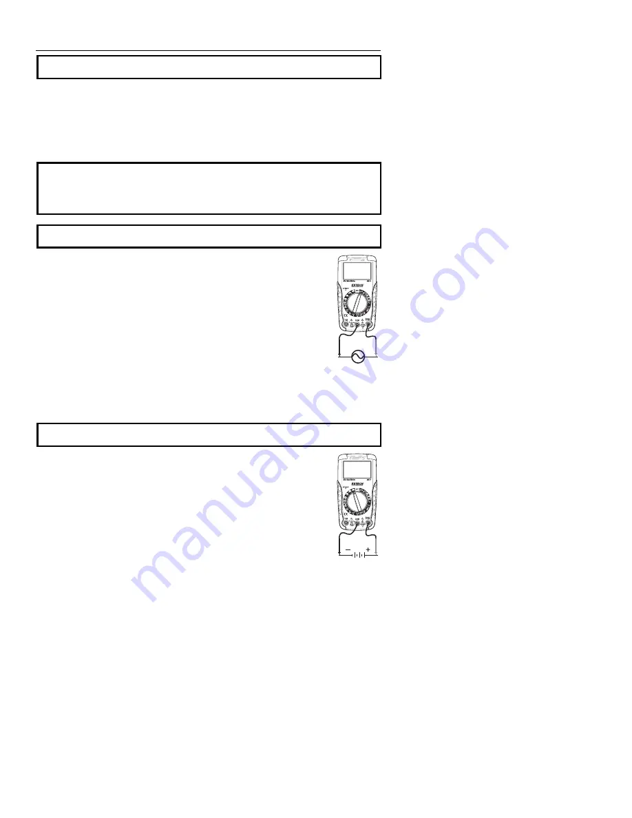
1. 

Set the function switch to the 600 VAC position. 

2.  Insert the black test lead banana plug into the negative 

COM

 jack. 

Insert red test lead banana plug into the positive 

V

 jack. 

3.  Touch the black test probe tip to the neutral side of the circuit.  
4.  Touch the red test probe tip to the “hot” side of circuit. 
5.  Read the voltage in the display.


6.  If the reading is less than 200V, switch to the 200V range to improve 

resolution. 


DC VOLTAGE MEASUREMENTS 

CAUTION:  

Do not measure DC voltages if a motor on the circuit is being switched ON or 

OFF. Large voltage surges may occur that can damage the meter. 

1. 

Set the function switch to the highest 600VDC position. 

2.  Insert the black test lead banana plug into the negative 

COM

 jack. 

Insert the red test lead banana plug into the positive 

V

 jack. 

3.  Touch the black test probe tip to the negative side of the circuit. Touch 

the red test probe tip to the positive side of the circuit. 

4.  Read the voltage in the display.  
5.  If the reading is less than the maximum of a lower range, switch to that 

range to improve resolution.  


Summary of Contents for MN15A

Page 1: ...User s Guide Mini Digital Multimeter Model MN15A A...

Page 2: ...symbol indicates that a device is protected throughout by double insulation or reinforced insulation SAFETY INSTRUCTIONS This meter has been designed for safe use but must be operated with caution The...

Page 3: ...jack for voltage milliamp resistance continuity diode and temperature functions 5 COM test lead jack 6 Battery compartment rear SYMBOLS Continuity Diode AC DC M megga 10 6 ohms m milli 10 3 volts amps...

Page 4: ...eing switched ON or OFF Large voltage surges may occur that can damage the meter 1 Set the function switch to the 600 VAC position 2 Insert the black test lead banana plug into the negative COM jack I...

Page 5: ...the 200mA position and insert the red test lead banana plug into the mA jack 3 For current measurements up to 10A set the function switch to the 10A position and insert the red test lead banana plug i...

Page 6: ...e potential 1 Set the function switch to the position 2 Insert the black lead banana plug into the negative COM jack Insert the red test lead banana plug into the positive jack 3 Touch the test probe...

Page 7: ...positive V jack 3 Touch the black test probe tip to the negative side of the battery Touch the red test probe tip to the positive side of the battery 4 Read the voltage in the display TEMPERATURE MEA...

Page 8: ...hould be removed to prevent damage to the unit BATTERY FUSE INSTALLATION and LOW BATTERY INDICATION WARNING To avoid electric shock disconnect the test leads from any source of voltage before removing...

Page 9: ...10A 10mA 2 0 reading 2 digits Resistance 200 0 1 0 8 reading 2 digits 2000 1 20k 0 01k 200k 0 1k 20M 10k 1 5 reading 2 digits Battery Test 9V 10mV 1 0 reading 2 digits 1 5V 1mV Temperature 20 C to 75...

Page 10: ...e insulation per EN61010 1 and IEC61010 1 2nd Edition 2001 to CAT III 600V Pollution Degree 2 The meter also meets UL 61010 1 Second Edition 2004 CAN CSA C22 2 No 61010 1 Second Edition 2004 and UL 61...

Page 11: ...sponsible for shipping charges freight insurance and proper packaging to prevent damage in transit This warranty does not apply to defects resulting from action of the user such as misuse improper wir...

Page 12: ...MN15A V1 1 02 09 12...

Reviews: