background image

MO270-EU-EN-v2.1   11/12 

12 

Alarm Operation 

  The HIGH and LOW Alarm limits are user programmable as described in the OPERATION 

(SETTINGS) section. Note that the High Alarm limit cannot be set lower than the Low Alarm limit 
and the Low Alarm Limit cannot be set higher than the High Alarm limit. 

  When an alarm is set to ON in the SETTINGS mode, the analyzer will indicate the alarm symbol 

(high or low) in black with the associated alarm value on the display (see the Display Icons 
section).  

  Once the high and low alarm limits are set, the analyzer will audibly and/or visually alarm (in 

flashing red) when a measurement limit is exceeded. Note that if the SOUND setting is turned 
OFF in the SETTINGS mode, only the visual alarm will trigger. 

  To silence an alarm, go to the ALARM sub-menu in the SETTINGS menu and select OFF for the 

alarm SOUND setting. 


Trend Analysis Display Feature 

  Press the F2-MODE soft-key once from the main analyzer display to access the Trend Analysis 

display mode.


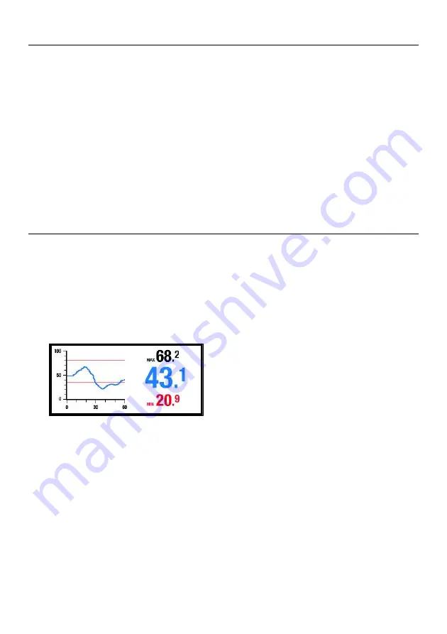
The Trend Analysis screen is shown below. 

  The digits on the right side of the Trend Analysis screen show the actual measurement (center), 

the highest reading (top), and the lowest reading (bottom) for a given measurement session. 

  The x-y graph on the left represents the measurements (vertical scale) over time (horizontal) 

  To begin a Trend session, press F3-START from the Trend Analysis screen (the red REC icon 

will be visible on the upper right hand corner of the display while the analyzer is trending). 

  Press the F3-STOP soft-key to stop a trending session (the REC icon will switch off). 


Summary of Contents for MO270

Page 1: ...User Guide Wireless Moisture Analyzer Model MO270...

Page 2: ...ing materials using pins that are driven into the material under test The Sensor unit transmitter detaches from the Analyzer unit receiver for remote measurement operation This analyzer is shipped ful...

Page 3: ...ve cap 7 Bluetooth capability 8 Includes two 2 3 7V rechargeable Li Polymer batteries one for Analyzer and one for Sensor wireless moisture Sensor unit external pin probe replacement pins telescoping...

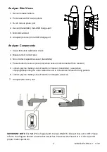
Page 4: ...r transmitter 4 Power button for sensor used only when sensor is disconnected from receiver 5 Lithium polymer battery shut off switch for Sensor transmitter used when shipping transporting the unit or...

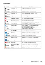
Page 5: ...BluetoothTM blue Active pairing Active BluetoothTM communication between receiver and peripheral device gray RF Wireless Wireless transmitter is ON sensor communication is INACTIVE orange RF wireless...

Page 6: ...r 2 Charging the batteries using a PC USB port a With the Analyzer ON OFF switch turned ON connect the USB cable between the mini USB port on the Sensor or the Analyzer and a USB port on the PC Note t...

Page 7: ...nsor into areas that are difficult or unsafe to reach Connect the sensor transmitter unit to the extender using the extender s mounting screw and the mounting screw hole on the sensor Note that extend...

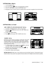
Page 8: ...T or BACK when done CHANNEL Setting Select the common channel over which a transmitter and receiver will communicate If several transmitters are owned a unique channel number can be used for each Note...

Page 9: ...ght arrow keys to move the triangle shaped pointer to the digit that is to be changed 4 Use the up down arrows to change the digit s value Press to store the new value and to switch off the arrow poin...

Page 10: ...keys to scroll over to the SCAN box for either the HIGH or the LOW Alarm limit When the SCAN box is highlighted press the button to automatically transpose the real time measurement to the Alarm limi...

Page 11: ...measurement of 50 is taken the meter will display 30 50 actual reading minus 20 reference reading 30 displayed reading Note The REL icon will flash on the measurement display screen while the ZERO fu...

Page 12: ...he SETTINGS mode only the visual alarm will trigger To silence an alarm go to the ALARM sub menu in the SETTINGS menu and select OFF for the alarm SOUND setting Trend Analysis Display Feature Press th...

Page 13: ...Use the CLEAR button to delete a displayed reading Press F1 BACK to return to the Groups list or press EXIT to return to the normal operating mode Rename a Memory Group To rename a memory group press...

Page 14: ...s device complies with part 15 of the FCC Rules Operation is subject to the following two conditions 1 This device may not cause harmful interference 2 This device must accept any interference receive...

Page 15: ...nt principle Electrical resistance pins Electromagnetic sensor pinless Measurement ranges 0 0 to 99 9 Relative pinless 7 0 to 99 3 WME pins Electrode pin length 0 75 22mm Electrode pin type Integrated...

Page 16: ...4 Boxwood Maracaibo 1 Kauri Queensland 8 Camphorwood E African 3 Keruing 5 Canarium African 2 Kuroka 1 Cedar Japanese 2 Larch European 3 Cedar West Indian 8 Larch Japanese 3 Cedar Western Red 3 Larch...

Page 17: ...rsimmon 6 Turpentine 3 Pillarwood 5 Utile 8 Pine American Long Leaf 3 Walnut African 8 Pine American Pitch 3 Walnut American 1 Pine Bunya 2 Walnut European 3 Pine Caribbean Pitch 3 Walnut New Guinea 2...

Page 18: ...Fraxinus Americana 2 Bosquiera phoberos 1 Fraxinus excelsior 1 Brachylaena hutchinsii 8 Fraxinus japonicus 1 Brachystegia spp 2 Fraxinus mardshurica 1 Calophyllum brasiliense 7 Gonystylus macrophyllu...

Page 19: ...18 28 mc 3 Thujopsis dolabrat 8 Picea jezoensis 8 18 mc 8 Tieghamella heckelii 2 Picea sitchensis 3 Tilia americana 6 Pinus caribaea 3 Tilia vulgaris 4 Pinus contorta 1 Triploehiton scleroxylon 6 Pin...

Page 20: ...MO270 EU EN v2 1 11 12 20 Appendix B Menu Structure User Interface...

Page 21: ...MO270 EU EN v2 1 11 12 21 Appendix B Menu Structure User Interface continued...

Reviews: