background image

RC200-EU-EN-V1.5-4/12 

3

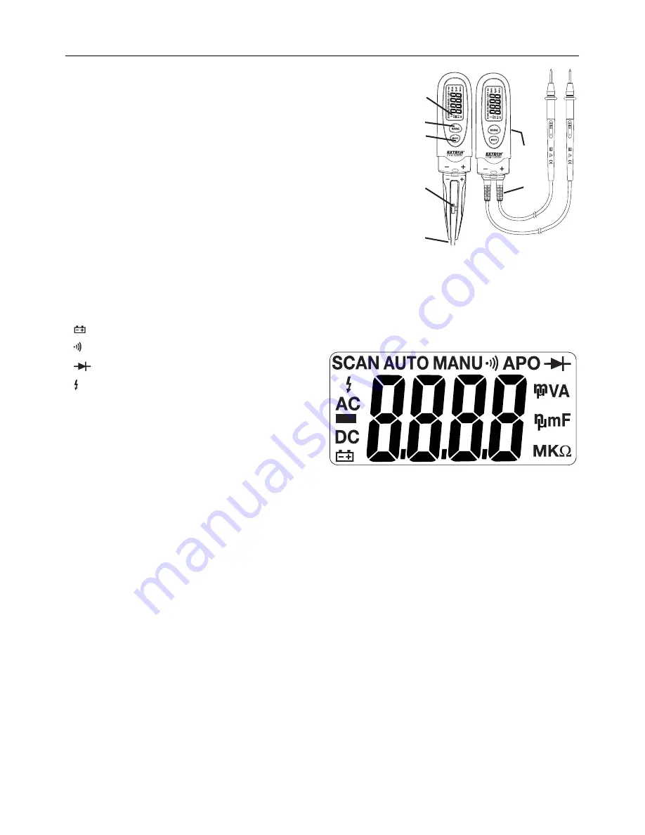
Description 

1. LCD 

display 

2. RANGE 

button 

3.  MODE and Power button 

4. Spacing 

adjustment 

5. Tweezer 

contacts 

6. Voltage 

adaptor 

7.  Batter compartment (rear) 


LCD Display Symbols 

 Low 

battery 

 Continuity 

 Diode 


>30V caution icon. 

n

 nano 

(10

-9

) (capacitance)  

µ

 micro 

(10

-6

) (amps, cap) 

m

 milli 

(10

-3

) (volts, amps) 

k

 kilo 

(10

3

) (ohms) 

F

 Farads 

(capacitance) 

M

 mega 

(10

6

) (ohms) 

 Ohms 


V

 Volts 

AC

 AC 

voltage 

DC

 DC 

voltage 

AUTO


Auto Range  

SCAN


SCAN  mode  

APO 

Auto power off enabled 


1

2

3

4

5

6

7

Summary of Contents for RC200

Page 1: ...User s Guide R C SMD Tweezers Multimeter Model RC200 ...

Page 2: ... current to the meter that exceeds the specified maximum Input Protection Limits Function Maximum Input V DC or V AC 600V DC AC 3 USE EXTREME CAUTION when working with voltages greater than 25VAC or 35VDC These voltages are considered a shock hazard 4 DO NOT measure voltage if the voltage on the COM input jack exceeds 600V above earth ground 5 NEVER connect the meter leads across a voltage source ...

Page 3: ... adaptor 7 Batter compartment rear LCD Display Symbols Low battery Continuity Diode 30V caution icon n nano 10 9 capacitance µ micro 10 6 amps cap m milli 10 3 volts amps k kilo 10 3 ohms F Farads capacitance M mega 10 6 ohms Ω Ohms V Volts AC AC voltage DC DC voltage AUTO Auto Range SCAN SCAN mode APO Auto power off enabled 1 2 3 4 5 6 7 ...

Page 4: ...uch the red test probe tip to the positive side of the circuit 5 Read the voltage in the display Note The DANGER symbol will appear in the display whenever the measured voltage exceeds 30V WARNING To avoid electric shock disconnect power to the unit under test and discharge all capacitors before taking any capacitance or resistance measurements Remove the batteries and unplug line cords Tweezer Re...

Page 5: ...ECOMMENDED SIZE AND TYPE Remove old or weak batteries so they do not leak and damage the unit 6 IF THE METER IS TO BE STORED FOR A LONG PERIOD OF TIME the batteries should be removed to prevent damage to the unit BATTERY INSTALLATION 1 Turn power off 2 Open the rear battery cover by removing the two Phillips head screws located on the rear of the meter 3 Insert the batteries into battery holder ob...

Page 6: ...V Bandwidth 50Hz to 60Hz Display 6000 count liquid crystal Overrange indication OL is displayed Polarity Automatic no indication for positive Minus sign for negative Auto Power Off 10 minutes approx Low Battery Indication is displayed if battery voltage drops below the operating voltage Batteries Two button batteries AG13 LR44 or equivalent Battery life Approximately 60 hours Operating Temperature...

Reviews: