background image

                                                                   11                          

RH520B-en-US_v5.2   8/20


Display Modes 

STANDARD VIEW 

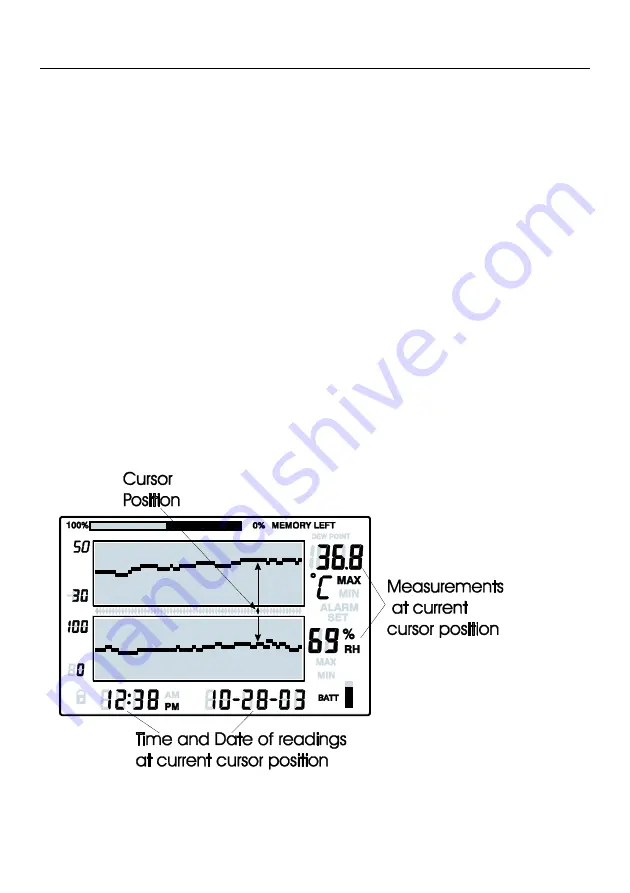
The Standard View is the display state of the RH520B when it is turned on. Refer to the diagram 
in the display description section of this manual for a representation of the Standard View. To 
reach the Standard View at any time, press the VIEW button. Note that the display automatically 
reverts to the Standard View five (5) minutes after the last button press. 

CURSOR 

The CURSOR location is indicated by a small diamond located between the two graphs.  See 
diagram. There is one diamond for each horizontal pixel in the graph (64 positions). The date, 
time, and measurements for the data point selected by the cursor are shown in the Time/Date 
and numerical measurement display fields. 


Each press of the RIGHT ARROW button will move the cursor to the right. When the cursor 
reaches the right-side limit, the graph will move to the left. Holding the button down will 
speed the scrolling rate. When the cursor reaches the oldest (last) reading, it will stop. 


Each press of the LEFT ARROW button will move the cursor to the left. When the cursor 
reaches the left side limit, the graph will move to the right. Holding the button down will 
speed the scrolling rate. When the cursor reaches the newest (latest) reading, it will stop. 


Each press of the UP ARROW button will shift the graph to the next set of 64 values; to the 
left of the ones currently displayed (the cursor will not move). 


Each press of the DOWN ARROW button will shift the graph to the next set of 64 values; to 
the right of the one displayed (the cursor will not move). 

Summary of Contents for RH520B

Page 1: ...USER MANUAL Paperless Humidity Temperature Chart Recorder Model RH520B Additional User Manual Translations available at www extech com...

Page 2: ...n Use protective gloves when necessary Do not short circuit batteries or discard them in a fire FCC Compliance This equipment has been tested and found to comply with the limits for a Class B digital...

Page 3: ...ack 7 AC adaptor jack 8 DATA RESET button clears recorded measurement data and alarm history 9 Temperature units select switch C or F 10 PROGRAMMING RESET button clears programming changes but retains...

Page 4: ...mits 4 Cursor Alarm indicators 5 Push button lock out status indicator 6 Time display 7 Relative Humidity RH measurement graph 8 Date display 9 Function indicators 10 Numerical temperature reading dis...

Page 5: ...n with other buttons to set new parameter values Stores new parameter values and returns to the Standard View TEMP Used in combination with other buttons to set the vertical graph range Used in combin...

Page 6: ...xit TEMP RH View Dew Point temp VIEW to exit ALARM Step back through ALARM points ALARM selects next Alarm VIEW to exit SET TEMP ALARM Enters Set TEMP Alarm mode ALARM selects HIGH LOW SET to save SET...

Page 7: ...tor has only one segment left the batteries must be replaced immediately NOTE Always set the Date Time and Sample rate immediately after batteries have been installed or after the RESET button in the...

Page 8: ...RE o C o F The oC oF switch located inside the battery compartment is used to select the unit of measure for temperature displays SETTING THE VERTICAL RESOLUTION FOR THE TEMPERATURE GRAPHIC DISPLAY 1...

Page 9: ...displays will switch off 5 The projected TIME and DAYS representing the moment the internal memory will be full based on the sample rate is displayed in the TIME and DATE display areas 6 Use the UP D...

Page 10: ...H alarm limit Use the LEFT RIGHT arrow buttons to step through the decades 4 Press the ALARM button The MIN low alarm indicator will switch on 5 Use the UP DOWN arrow buttons to increment decrement th...

Page 11: ...Time Date and numerical measurement display fields Each press of the RIGHT ARROW button will move the cursor to the right When the cursor reaches the right side limit the graph will move to the left H...

Page 12: ...the MAX or MIN indicator is ON under the RH reading digits the display is showing the MAX or MIN relative humidity ALARM DISPLAYS 1 Press the ALARM button from the Standard View to analyze the most re...

Page 13: ...time of day 3 The temperature and humidity readings for the selected Time will display 4 Press VIEW to return to the Standard View DEW POINT DISPLAY Press the TEMP and the RH buttons simultaneously t...

Page 14: ...AYS that the internal memory will be full based on the current sample rate is displayed in the TIME and DATE display areas 4 To change the sample rate refer to the programming section of this manual 5...

Page 15: ...r allows the user to track the status of the battery When all 5 segments are dark the battery is fully charged Segments switch off as the battery ages When the battery indicator has only one segment l...

Page 16: ...tion 5 segment battery indicator Alarm output 3 5mm Mono Phone Plug Maximum 3 4mA 5 VDC Minimum Output Voltage 2 5 VDC Power supply Three 3 AA batteries and AC adaptor included DC 5V 1A 3 5mm x 1 35 m...

Page 17: ...ration for most of our products Contact us for information on calibration and repair availability refer to the contact information below Annual calibrations should be performed to verify meter perform...

Reviews: