WEVP 630 E BIS WIRING
any electric catch or lock that you install must be fitted with a mechanical memory like that on all Extel models • for wiring
instructions, refer to the label on the back of the monitor and the back of the camera.
b. Connection of an electric catch or lock
If the installation is to include an electric catch or lock, two more wires will have to be added to connect the
catch or lock to the monitor.
Connect them to terminals 5 and 6 of the monitor.
NB: the power supply to the electric catch or lock is to be provided by an independent transformer which is
not supplied in the kit (Extel ref.: WETR 14602).
NB: this function can only be used if the monitor is connected to a power supply.
6
4
1
2
2
3
4
3
6
5
Seal the upper joint between the exterior plate and the wall with silicone .
5
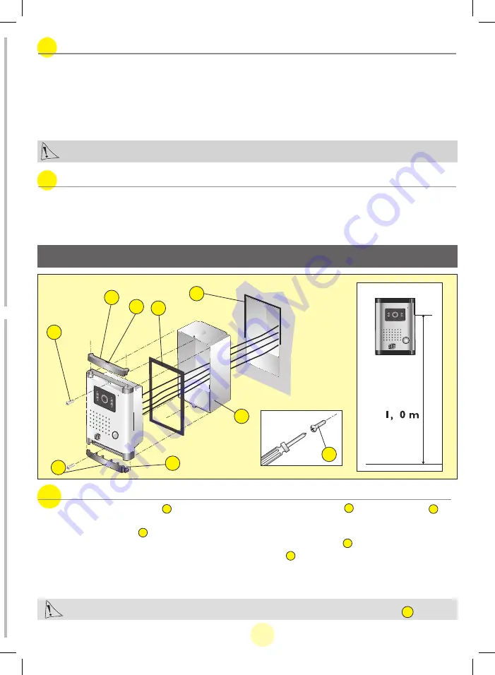
a. Installation of the oudoor station (camera)
1. Remove the two screw covers using a small screwdriver lodged in the notch . Remove the two
screws.
2. Insert the plastic casing taking care not to obstruct the plate fixation holes.
3. Connect the cable as shown in the wiring diagram with the waterproof gasket in place.
4. Screw the plate onto the inserted casing using the two screws .
5. Put the two screw covers back.
Make sure that the camera lens is not pointing directly at the sun or at a reflective surface.
1
2
6
6EN
c. Connection of a gate mechanism
Connect it directly to terminals 5 and 6 on the back of the monitor. The monitor provides a current-free “dry”
contact on your mechanism's “push button” function.
NB: this function can only be used if the monitor is connected to a power supply
4. INSTALLATION
4
3
4
Summary of Contents for WEVP 630 E BIS
Page 1: ......


