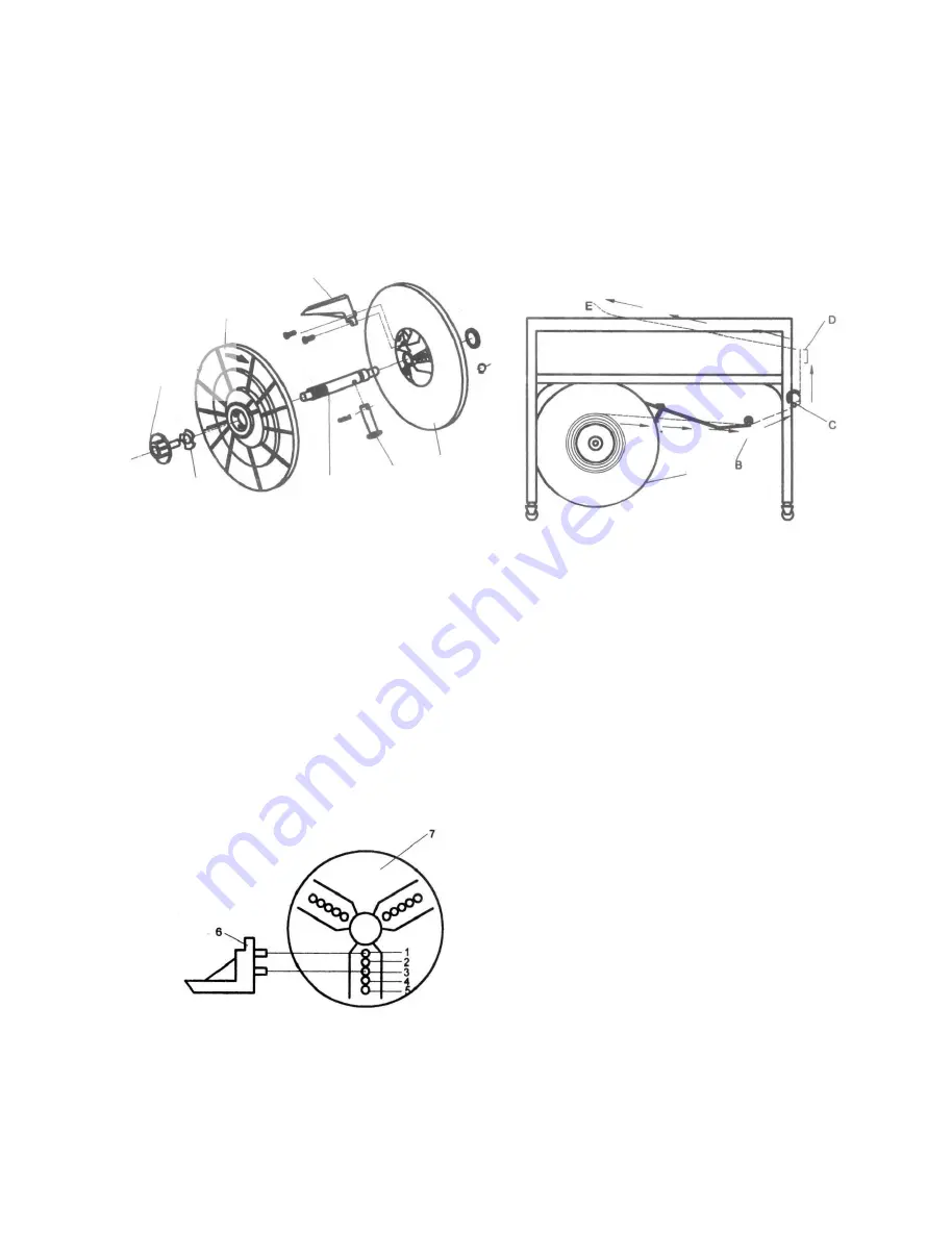
5. Replace the Plastic B and reinstall the Reel nut hand
wheel.
6. At this time the securing straps can be removed from the
coil of strap.
7. Place the dispenser assembly back into the rearend of
the machine, Make sure the assembly is placed in
properly. The Reel nut hand wheel should be positioned
to the right. This can be verified by noting that the drag
arm of the friction brake contacts the Plastic flange A.
8. When installed, close the rear panel door.
1. Open the right-hand door and pull about 3 feet (1M)of
strap from the coil.
2. Thread the strap through the looper (B), pass it under
roller (C) and allow it to exit the cabinet. Close the
right-hand door.
3. Pull up on the strap, then insert the lead-end between
the guide and roller (D).
4. Continue to push the strap through the head until it
can be seen at point (E).
FLANGE
PLASTIC
REEL CENTER
CLAW
REEL UNT
HANDWHEEL
Y-TYPE
WASHER
FIGURE 7. DISPENSER ASSEMBLY
DISPENSER
SHAFT
PLASTIC
FLANGEA
PIN
FIGURE 9. STRAP THREADING DIAGRAM
STRAPPING CYCLE
The machine is now ready for strapping a
package.
To operate the EXS-206, proceed as follow:
1. Push the power switch to the “NO” position and
allow the hot knife 5 seconds to reach operating
temperature.
2. Place a package on the table top, directly above
the sealing head. Allow the package to contact
the two package stops.
3. Grasp the strap on the left side on the package,
bring it over the package and insert the lead-end
into the strap closes LS1, the strap will be
tensioned, welded and then released, all
automatically. “CAUTION!!” Be sure to keep
fingers from beneath the strap.
Please follow instruction below to adjust the Reel center
claw (part NO. #4-07000-130) for various inner coils.
Refer to Fig. 8:
1. For 200mm inner coil diameter, position 2 holes on
the Reel center claw ( Item 6 ) to #1 and #3 holes of
the Plastic Flange A (Item 7).
2. For 230mm inner coil diameter, position 2 holes on
the Reel center claw ( Item 6 ) to #2 and #4 holes of
the Plastic Flange A (Item 7).
3. For 280mm inner coil diameter, position 2 holes on
the Reel center claw ( Item 6 ) to #3 and #5 holes of
the Plastic Flange A (Item 7).
FIGURE 8. THREADING STRAP THROUGH MACHINE
4. Remove the strapped package and note the
length of the strap fed out for the next cycle.
Adjust the time as needed.
5. Note the condition of the weld and the tension of
the tie on the package, If the condition of the weld
or the level of tension is unsatisfactory, adjust the
hot knife temperature or the tension level as
needed. Ref: Operating Adjustments.
The threading procedure involves routing strap from the
dispenser and up through the strapping head.
Refer to Figure 9 and proceed as follows:
-6-
All manuals and user guides at all-guides.com


