Chapter 8 – Troubleshooting
User Manual
75
Vortex
®
Precedence
Rev 3.6
Issue
Cause
Resolution
Part is marked
after completion
Debris in upper or lower tool
Clean upper and lower tooling.
Part was presented to the
machine with damage
Check parts for marks before and after
processing.
Tool or details on tool may be
loose.
Check all fasteners and verify tightness.
Use blue loc-tite to retain fasteners that
come loose frequently.
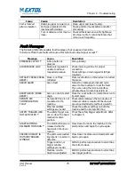
Fault Messages
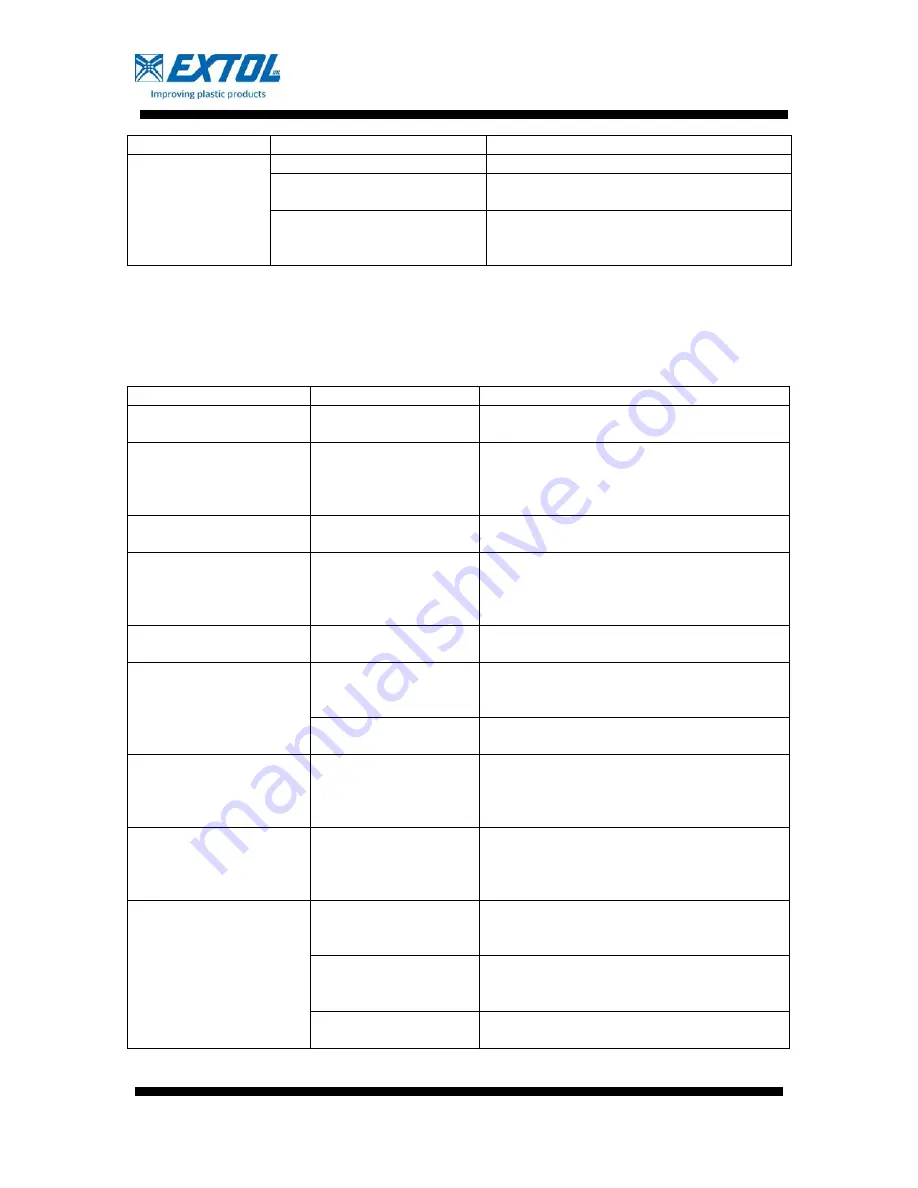
The following table lists possible fault messages, their cause and resolution.
In Remote Mode these faults will cause a Machine Fault output signal, except *.
Message
Cause
Resolution
EMERGENCY STOP! *
E-Stop button is
pressed.
Pull up E-Stop
AIR PRESSURE LOW
Electronic regulator is
unable to achieve
requested pressure
Check incoming air line for proper
connection.
Check setting on main regulator (85 psi
required).
RETRACT PRESS (PRESS
RESET)
Press is not fully
retracted
Press reset button on Main screen to retract
the press.
SERVO ALARM
Servo fault
Follow the message prompt and cycle
power to the machine to reset the fault.
If you are using the remote interface,
activate the servo reset input (Pin 8)
RESET SERVO (PRESS
RESET)
Servo is not at its start
angle.
Press the reset button to rotate the servo to
its start angle.
REMOTE SPC
COMMUNICATION
FAULT
Remote SPC box is not
connected to the
machine.
Check cables between the two devices. A
crossover cable is required if the devices
are connected directly (without a switch).
Ethernet address
settings are invalid.
Check the address settings on both the
machine and the Remote SPC box.
SAFETY TRIGGER WAS
NOT ACTIVATED *
The safety trigger was
not on when the head
reached its down
position.
Check the safety trigger adjustment. Refer
to Chapter 5.
START BUTTONS
RELEASED TOO SOON *
The start buttons were
released while the
head was in its down
motion.
Press Reset to return the machine to the
start position and begin the cycle again.
PREWELD HEIGHT IS
OUTSIDE TRIGGER
WINDOW
The parts were loaded
improperly or parts are
defective.
Press Reset. Examine and reload parts and
begin cycle again.
Trigger position or
trigger window
settings are invalid
Perform part setup procedure to determine
the correct values.
Machine column
height was adjusted.
Perform part setup procedure to determine
new trigger position.
Summary of Contents for VORTEX PRECEDENCE G1
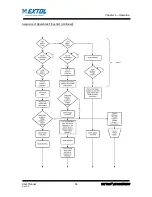
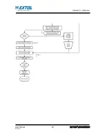
Page 66: ...Chapter 6 Operation User Manual 60 Vortex Precedence Rev 3 6 Sequence of Operations Flowchart ...
Page 69: ...Chapter 6 Operation User Manual 63 Vortex Precedence Rev 3 6 ...
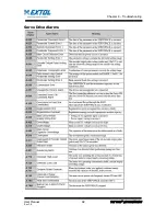
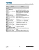
Page 88: ...Chapter 8 Troubleshooting User Manual 82 Vortex Precedence Rev 3 6 Servo Drive Alarms ...
Page 89: ...Chapter 8 Troubleshooting User Manual 83 Vortex Precedence Rev 3 6 ...
Page 90: ...Chapter 8 Troubleshooting User Manual 84 Vortex Precedence Rev 3 6 ...
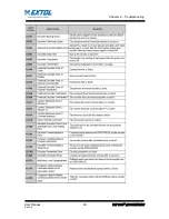
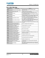
Page 91: ...Chapter 8 Troubleshooting User Manual 85 Vortex Precedence Rev 3 6 Servo Drive Warnings ...
Page 104: ...651 Case Karsten Drive Zeeland MI 49464 1 800 324 6205 www extolinc com ...

