background image

26

ENGLISH

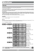
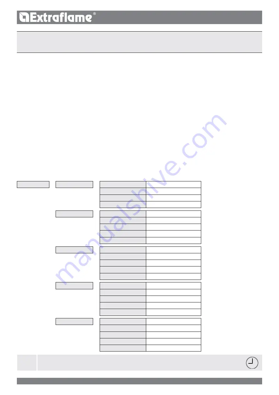
chrono

>

enaBlinG

>

PrG1

ON/Off

enable/disable prg 1

>

PrG2

ON/Off

enable/disable prg 2

>

PrG3

ON/Off

enable/disable prg 3

>

PrG4

ON/Off

enable/disable prg 4

PrG1

>

sTarT PrG1

Off-00:00

Ignition time prg1

>

sToP PrG1

Off-00:00

Switch-off time prg1

>

Monday...sUnday

ON/Off

enable/disable the days of prg1

>

seT PrG1

 65°C - 80°C (149°f - 176°f)

SeT h2O prg1

>

Power PrG1

1-5

Set power prg1

PrG2

>

sTarT PrG2

Off-00:00

Ignition time prg2

>

sToP PrG2

Off-00:00

Switch-off time prg2

>

Monday...sUnday

ON/Off

enable/disable the days of prg2

>

seT PrG2

 65°C - 80°C (149°f - 176°f)

SeT h2O prg2

>

Power PrG2

1-5

Set power prg2

PrG3

>

sTarT PrG3

Off-00:00

Ignition time prg3

>

sToP PrG3

Off-00:00

Switch-off time prg3

>

Monday...sUnday

ON/Off

enable/disable the days of prg3

>

seT PrG3

 65°C - 80°C (149°f - 176°f)

SeT h2O prg3

>

Power PrG3

1-5

Set power prg3

PrG4

>

sTarT PrG4

Off-00:00

Ignition time prg4

sToP PrG4

Off-00:00

Switch-off time prg4

Monday...sUnday

ON/Off

enable/disable the days of prg4

seT PrG4

 65°C - 80°C (149°f - 176°f)

SeT h2O prg4

Power PrG4

1-5

Set power prg4

cHrOnO

This function allows stove ignition and switch-off to be automatically programmed.

The factory setting for cHRono is off.
The chrono allows the programming of 4 time slots per day, which can be used every day of the week. 

For each time slot, it is possible to 

set ignition and switch-off times, specific days of application, desired temperature and set power. current day and time settings 

are essential for the correct operation of the chrono.

recommendations
Before using the chrono function, you must set the current date and time, so check that you have followed the points listed in the sub-

chapter “daTe-TiMe”. To use the chrono function correctly, it must not only be programmed, but also enabled. The 4 time slots can be 
overlapped using the ignition and switch-off time settings. in this way, it is possible to create a combination of time slots with different 

temperatures and power levels, without changing the status of the stove. 

n.B.: in the case of overlapping time slots, the stove will remain on until the last switch-off time. 

PrG 1-4

The switch-on and switch-off time along with the days of use of the programmed time slot and the desired water temperature (65 - 80°c) can 

be set. current day and time settings are essential for the correct operation of the chrono.

To set: 

OK > 

seT chrono

 > 

seT PrG1-4

.

enaBlinG

Allows the chrono and the different stove time slots to be enabled/disabled.

To set: 

OK > ChrONO > eNaBLINg.

J

WHen tHe Weekly prOGrammer Is actIve, tHe relatIve IcOn WIll Be sHOWn On tHe radIO 

cOntrOl dIsplay.

Summary of Contents for 001282105

Page 1: ...MADE IN ITALY design production FIANDRA IDRO EVO 004280684 rev 000 ENGLISH UK THERMO PRODUCTS USER MANUAL ...

Page 2: ...2 ENGLISH APPLY TECHNICAL DATA LABEL ...

Page 3: ...3 ADDITIONAL THERMOSTAT 24 Additional thermostat functioning with STAND BY active 24 Additional thermostat operation with STAND BY deactivated 24 ADDITIONAL THERMOSTAT INSTALLATION 24 Ventilation 25 EASY SETUP 25 CHRONO 26 prg 1 4 26 SETTINGS 28 Display 28 STAND BY 28 FIRST LOAD 28 OUTLET AIR 28 CLEANING 28 Reset 29 EASY CONTROL 29 DEPRESSURE NOTICE 29 ADDITIONAL FUNCTIONS 29 Optional additional d...

Page 4: ...e bouger le poêle faire attention à lever les céramiques indiquées pour éviter des dégâts VORSICHT OBLIGATORISCH Bevor Sie den Ofen bewegen bitte unbedingt die bezeichnete Keramik Kacheln entfernen um Schäden zu vermeiden ATENCIÓN PERENTORIO Antes de mover la estufa sacar las mayólicas indicadas para evitar daños UWAGA OBOWIĄZEK Przed przystąpieniem do przemieszczania pieca zdjąć wskazane majoliki...

Page 5: ...iance has been installed as well as the instructions contained in this manual The use of the appliance must comply with all local regional national and European regulations The Manufacturer cannot be held responsible for the failure to comply with such precautions After removing the packaging ensure that the content is intact and com plete Otherwise contact the dealer where the appliance was purch...

Page 6: ...N IF IT IS DISCONNECTED FROMTHE MAINS It is advised to position the power supply cable so that it does not come into contact with hot parts ofthe appliance The power supply plug must be accessible after installation Do not close or reducethe dimensions ofthe airingvents in the place of installation The airing vents are essential for correct combustion Do not leave the packaging elements within rea...

Page 7: ... clean the majolicas it is recommended to use a soft dry cloth If a detergent or liquid is used the latter could penetrate inside the crackles highlighting them SINCE THE PRODUCT CAN TURN ON AUTOMATICALLY THANKS TO THE TIMER OR REMOTELY USING THE DEDICATED APPLICATIONS IT IS STRICTLY FORBIDDEN TO LEAVE ANY COMBUSTIBLE OBJECT WITHIN THE SAFETY DISTANCES INDICATED ON THE TECHNICAL DATA PLATE interna...

Page 8: ...omestichotwaterproductionandinadjacentandcommunicating rooms 3 where the depression measured in situ between the external and internal environment is greater than 4 Pa N B Watertight appliances can also be installed in the cases indicated in points 1 2 and 3 of this paragraph Installations in bathrooms bedrooms and studio flats Installation in bathrooms bedrooms and studio flats is only allowed fo...

Page 9: ...t always be insulated The smoke ducts must have at least one airtight inlet for flue gas sampling All the sections of the flue gas duct must be accessible to inspection Inspection openings must be provided for cleaning If the generator has a fume temperature lower than 160 C ambient temperature caused by the high yield contact technicians it MUST be resistant to humidity Afluesystemthatdoesnotresp...

Page 10: ...e houses because it does not take air in from within the house combustion air To ensure the stove remains hermetically sealed the connection pipe for the combustion air must be directly connected to the exterior using special pipes and sealed connectors For an hermetic installation is necessary to contact a qualified installer FUMES EXHAUST SYSTEM If the generator has a fumes temperature of less t...

Page 11: ...g and inspection of correct functioning must be carried out perfectly in full compliance with Standards in force national regional and municipal as well as these instructions For Italy installation must be carried out by professionally qualified staff Ministerial Decree dated 22 01 08 n 37 Extraflame S p A declines all responsibility for damage to objects and or persons caused by the system Type o...

Page 12: ...e This is to prevent unexpected power increases The flue fitting can be mounted between the boiler and the flue only after this inspection An inspection of the connections with pre existing flues is recommended ANTI CONDENSATION DEVICE MANDATORY Make sure a suitable anti condensate circuit has been realised which guarantees an appliance return temperature of at least 55 C The automatic thermostati...

Page 13: ...fety drain T2 Boiler flow output T3 Boiler return input Combustive air input Room air outlet Pellet hopper Heat exchanger scrapers Door handle Fumes exhaust Radio emergency card fuse Power supply 230v On Off Heat exchanger scrapers Room air outlet Access to the ash drawer ...

Page 14: ...ying motor and therefore operation of the heat generator The system must be bled several times to eliminate the air and loaded when the pressure is too low It is not an anomaly but normal phenomenon due to filling Following filling the system must always be bled using the relevant vents in the circuit and having the machine perform the air vent function Following commissioning and with the machine...

Page 15: ...tion means that you have 60 to close the hatch door and the pellet lid If this is not the case during ignition the stove will go to DEPRESSION ALARM mode while during normal operation the stove will go to COOLING WAIT mode and then re start automatically when the correct conditions are present stove cold etc Stove positioning For correct product functioning it is recommended to position it in a wa...

Page 16: ...ALITY PELLETS OR ANY OTHER MATERIAL DAMAGES THE FUNCTIONS OF THE GENERATOR AND CAN VOID THE WARRANTY AND THE ANNEXED RESPONSIBILITY OF THE MANUFACTURER Pellet tank During the operation of the stove the pellet tank cover must always remain closed Keep it clean Do not place the bag directly on the stove to load the tank Always use a scoop to load the tank Do not rub or place weights on the tank seal...

Page 17: ...e off LED on with fixed light stove in P1 2 3 and working Flashing LED stove in P1 2 3 and in switch off alarm stby P2 Power increase L3 LED off stove off LED on with fixed light stove in P3 4 5 and working Flashing LED stove in P3 4 5 and in switch off alarm stby P3 On off stove L4 Led off normal operation Led on alarm present L5 Led off radio communication not available Led on radio communicatio...

Page 18: ...r on the display In this case repeat the procedure J The radio control device is already CONFIGURED with unit 0 IF THERE IS ANOTHER STOVE to avoid interferences A NEW CONFIGURATION MUST BE PERFORMED modifying one of the two stoves Some radio frequency devices e g mobile phones etc may cause interference with communication between the radio control device and the stove Respect the environment Used ...

Page 19: ...on Do not place the radio control device in direct or indirect contact with water The radio control device may not work properly in the presence of humidity or if exposed to water FREQUENCY BANDS MAXIMUM POWER TRANSMITTED 868 3 MHz 4 mW ERP 869 85 MHz 4 mW ERP 1 Display 2 Set power scroll across in menus increase select a setting 3 Set H2O scroll across in menus reduce deselect a setting 4 Back ke...

Page 20: ...in the boiler Set water temperature H2O set Display text Water temperature H2O detected in the boiler Set H2O temperature set Power 1 5 Time Chrono active Stby active Battery low Temperature detected in environment by handheld device Set room temperature display text Power 1 5 Time Chrono active Stby active Battery low ...

Page 21: ...ct manual and with the relevant regulations in force The pellet hopper must be fully loaded The combustion chamber and the burn pot must be clean Make sure that the fire holder the ash drawer and the pellet hopper close hermetically if present in the hermetic version they must be closed and there must be no foreign bodies in the sealing elements and gaskets Check that the power cord is properly co...

Page 22: ... the part Replacement does not fall within the product warranty as the part is subject to wear DATE TIME This menu allows the date and time to be set To set OK Settings Date Time LANGUAGE This menu allows the preferred language to be selected To set OK Settings Language The languages available are Italiano English Deutsch Français Español Português Dansk Eesti Hrvatski Slovenscina Nederlands Polsk...

Page 23: ...e to overheating Normally this area is defined as the safety zone Room Temperature in the models envisioned It is possible to activate deactivate the front ventilation and control the room temperature via the Room probe integrated in the handheld device See the chapter ventilation on the following pages Burn pot cleaning During the working phase the stove has an internal timer which after a pre se...

Page 24: ... the stove and relative factory setting restrictions If the stove is in H OFF water temperature reached any additional contact or thermostat request will be ignored Additional thermostat operation with STAND BY deactivated When the STAND BY function is not active the STBY icon will be off When the contact or external thermostat is satisfied open contact temperature reached the stove will go to min...

Page 25: ...sing the preset values In the stove program the available values range from 3 to 3 all stoves are calibrated during production with the optimal value which is 0 If you notice an excessive deposit on the burn pot access the Easy setup program and lower the value by one unit to 1 then wait until the next day and if there is no improvement decrease again to a maximum of 3 Instead if it is necessary t...

Page 26: ...the programming of 4 time slots per day which can be used every day of the week For each time slot it is possible to set ignition and switch off times specific days of application desired temperature and set power Current day and time settings are essential for the correct operation of the Chrono Recommendations Before using the chrono function you must set the current date and time so check that ...

Page 27: ...0 t 3 1 02 00 23 00 08 00 16 30 t 72 68 2 1 27 ENGLISH Time slot 1 Start 02 00 Stop 23 00 Power 3 SET H2O 72 C Time slot 2 Start 08 00 Stop 16 30 Power 1 SET H2O 68 C Stove operation TIME SLOT SET POWER SET H2O EXAMPLE OF CHRONO OVERLAPPING TIMES SLOTS ...

Page 28: ...pt continuous loading simply press the key OK for 3 seconds To set OK Settings First load J REMEMBER ALWAYS TO COMPLETELY EMPTY THE BURN POT BEFORE IGNITION AND THAT THE HOLES IN THE BURN POT ARE ALL FREE NEVER EMPTY THE BURN POT INSIDE THE PELLET HOPPER FIRE RISK OUTLET AIR This function allows any air in the stove to be discharged By activating the pump function it will be powered alternatively ...

Page 29: ... if the door or the hopper are open Please note Activation can reduce battery life by 30 The battery life depends on the usage To set OK Settings DEPRESSURE NOTICE ADDITIONAL FUNCTIONS Optional additional data sheet The manufacturer has an optional additional data sheet which allows the boiler to have the following additional system management functions The table below indicates the various possib...

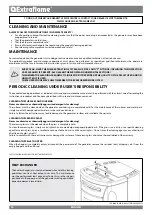
Page 30: ...te the warranty CLEANING THE CERAMIC GLASS Never use abrasive or chemically aggressive detergents for cleaning The ceramic glass must be cleaned when the glass is completely cold To clean the ceramic glass simply use a dry brush and some damp newspaper dipped in ash If the glass is very dirty use a specific cleaning agent for ceramic glass Spray a small amount on a cloth and use it on the ceramic ...

Page 31: ...ting it at the back A Clean the combustion chamber and the bottom of the burn pot completely using a suitable vacuum cleaner Refit the ash conveyor by performing the same operation in reverse Always make sure that that the ash conveyor rests on the burn pot correctly and not on another area of the combustion chamber the ash conveyor is installed in the correct direction for pellet feed the ash con...

Page 32: ...ds to be vacuumed and cleaned If there are horizontal sections the residue must be removed to prevent it from obstructing the flow of fumes SHUT DOWN END OF SEASON At the end of each season before turning the stove off it is advisable to completely empty the pellet hopper removing any pellet residue and dust with a vacuum cleaner IT IS ADVISABLE NOT TO DISCONNECT THE GENERATOR FROM THE POWER SUPPL...

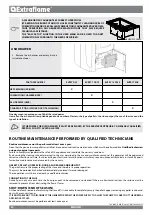
Page 33: ... and door replace and apply silicone where indicated C Combustion chamber and heat exchanger full cleaning including ignition plug pipe D Hopper complete emptying and cleaning E Check air intake pipe and cleaning of the flow sensor F Remove the room air fan and remove any dust and pellet residue TO FIND OUT WHERE YOUR NEAREST SERVICE CENTRE IS CONTACT YOUR DEALER OR VISIT THE WEBSITE WWW LANORDICA...

Page 34: ...e passed the stove will enter DEPR ALARM during the ignition phase while during normal operation the stove will enter COOLING STAND BY and then restart automatically when the conditions are met cold stove etc T OFF Generator off waiting for re ignition due to all requests met BLACK OUT STAND BY The generator is cooling after a power cut Once cooling is completed it will re start automatically ANTI...

Page 35: ...The system pressure read by the pressure switch is too low Possible air in the system bleed the system Possible lack of water or leaks due to anomalies in some system component If the problem persists contact the service centre H2O PROBE H2O probe fault Contact after sales centre MAX H2O PRESSURE ALARM The pressure of the water has exceeded the max threshold Possible air in the system bleed the sy...

Page 36: ... kindly asked to separate this equipment and or batteries or accumulators included from other types of waste and to arrange for disposal by the municipal waste service It is possible to ask your local dealer to collect the waste electric or electronic appliance under the conditions and following the methods provided by national laws transposing the Directive 2012 19 EU Separate waste collection an...

Page 37: ...37 ENGLISH ...

Page 38: ...38 ENGLISH ...

Page 39: ...39 ENGLISH ...

Page 40: ...Y 39 0445 865911 39 0445 865912 info extraflame it www lanordica extraflame com TO FIND THE SERVICE CENTRE NEAREST TO YOU CONTACT YOUR DEALER OR CONSULT THE SITE WWW LANORDICA EXTRAFLAME COM The manufacturer reserves the right to vary the characteristics and the data reported in this pamphlet at any moment and without notice in order to improve its products ...

Reviews: