16
S
UMMIT
V
IRTUAL
C
HASSIS
D
ESIGN
AND
I
NSTALLATION
G
UIDE
S
UPPORTED
C
ONFIGURATIONS
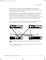
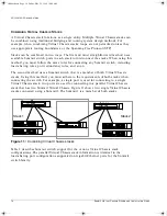
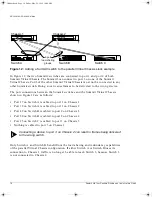
Figure 12: Adding a Summit3 switch to the parallel Virtual Chassis stack example
In Figure 12, the two Summit2 switches are connected to port 1 and port 2 of both
Summit Virtual Chassis. The Summit3 can connect to port 3 on one of the Summit
Virtual Chassis. Port3 of the other Summit Virtual Chassis must not be connected to any
other Summit switch. Doing so can cause frames to be delivered to the wrong device.
The port connections between the Summit switches and the Summit Virtual Chassis
shown in Figure 12 are as follows:
•
Port 17 on Switch A is cabled to port 1 on Chassis 1.
•
Port 18 on Switch A is cabled to port 1 on Chassis 2.
•
Port 49 on Switch B is cabled to port 2 on Chassis 1.
•
Port 50 on Switch B is cabled to port 2 on Chassis 2.
•
Port 25 on Switch C is cabled to port 3 on Chassis 1.
•
Nothing is cabled to port 3 on Chassis 2.
Connecting a device to port 3 on Chassis 2 can result in frames being delivered
to the wrong switch.
Only Switch A and Switch B benefit from the load-sharing and redundancy capabilities
of the parallel Virtual Chassis configuration. If either Switch A or Switch B loses its
connection to Chassis 1, traffic is no longer be able to reach Switch 3, because Switch 3
is not connected to Chassis 2.
Switch A
Switch C
Switch B
Chassis 2
Chassis 1
2-port
load-sharing
groups
virtchas.book Page 16 Friday, May 29, 1998 10:08 AM

