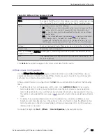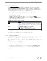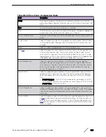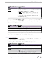
Figure 6: VLAN Example Network Diagram
Using the Web Interface to Configure VLANs
1 Access the
Switching
>
VLAN
>
Status
page.
2 Click
Add
to create a new VLAN.
3 Type
2-3
in the VLAN ID-Individual/Range field.
4 Click
Submit
.
5 From the Port Configuration Page, select VLAN 2 from the VLAN ID List.
6 From the Participation column in the interface table, select Include for ports 1/0/1 and 1/0/2 to
specify that these ports are members of VLAN 2.
7 Select the interface checkbox and click
Edit
. Select the Tagging All checkbox to specify that frames
will always be transmitted tagged from ports that are members of VLAN 2.
8 Click
Submit
.
9 Select VLAN 3 from the VLAN ID and Name List.
10 Select the Participate option in the VLAN field.
11 For ports 1/0/2, 1/0/3 and 1/0/4, select Include from the Participation menu to specify that these
ports are members of VLAN 3.
12 Click
Submit
.
13 Go to the
Switching
>
VLAN
>
Port Configuration
page.
14 From the Interface menu, select 1/0/1.
15 In the Acceptable Frame Types field, select AdmitTaggedOnly to specify that untagged frames will
be rejected on receipt.
16 Click
Submit
.
17 From the Interface menu, select 1/0/2.
18 In the Port VLAN ID field, enter
3
to assign VLAN 3 as the default VLAN for the port.
Configuration Examples
ExtremeSwitching 200 Series: Administration Guide
332


