4-5
SMX System Multimatrix Switcher • Programmer’s Guide
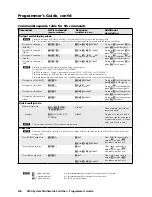
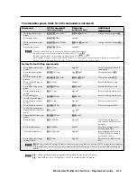
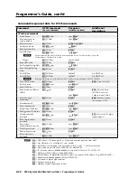
Using the Command/Response Table for SIS Commands
The command/response table begins on page 4-8.
Lowercase letters are acceptable
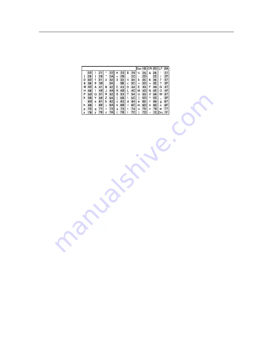
in the command field except where indicated. The table below shows the
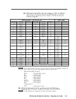
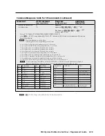
hexadecimal equivalent of ASCII characters used in the command/response tables.
ASCII to HEX Conversion Table
•
space
ASCII to hexadecimal conversion
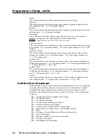
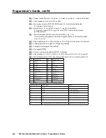
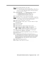
Symbols are used throughout the table to represent variables in the command/
response fields. Command and response examples are shown throughout the table.
Symbol definitions
]
= Carriage return with line feed
¦
or
}
= Carriage return with no line feed
•
= Space
E
or W = Escape key
N
Input and output numbers in commands may be entered as either 1-digit,
2-digit, or 3-digit numbers. All input and output numbers are reported as
2-digit numbers in the response (e.g., 03 for input 3).
X!
= Input number (1 through maximum number of inputs)
X@
= Input number (for ties; 0 through maximum number of inputs)
N
Input 0 = untied
X#
= Output number (1 through maximum number of outputs)
X$
= Numeric dB value
(-18 t24, 43 steps of gain or attenuation)
X%
= Audio gain (0 dB through 24 dB)
X^
= Audio attenuation (1 dB through 18 dB)
X&
= Volume adjustment range (0% to 100%) in 1 dB steps.
Volume max = 64 (default), volume min = 0
X*
= Fiber optic transceiver module: 0 =no module installed, 1 multimode module,
2 = singlemode module
X(
= On/off status (muting, executive mode, power supply, etc.)
muting/power supply: 0 = off/disabled, 1 = on/enabled
executive mode: 0 = enable (basic and admin), 1 = disabled front panel,
2 = enabled (basic only)
X1)
= Output rate: ####.##, where: ---- = bypass mode, 0000 = no connection
(rate mis-match), nnnn = actual rate
X1!
= Global/plane preset #: (0 = current configuration) [32 max global preset,
10 max plane preset]
X1#
= Delay in 0.5 second increments [10 max = 5.0 seconds]

