Installation, cont’d
SMX System MultiMatrix Switchers • Installation
2-8
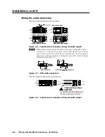
Wiring the audio connectors
Wire the input connectors as shown below.
Unbalanced Stereo Input
Tip
Sleeve
Sleeve
Tip
L
R
Unbalanced Mono Input
Balanced Mono Input
L
R
Tip
Ring
Sleeve
Tip
Ring
L
R
Tip
Sleeve
Tip
Sleeve
Balanced Stereo Input
L
R
Tip
Ring
Sleeve
Tip
Ring
Do not tin the wires!
Figure 2-6 — Captive screw connector wiring for audio signals
N
When making connections for the SMX switcher from existing audio cables,
see figure 2-7. A mono audio connector consists of the tip and sleeve, whereas
a stereo audio connector consists of the tip, ring and sleeve. The tip, ring, and
sleeve wires are also shown above on the captive screw audio connector diagram
(balanced inputs), figure 2-6.
Tip (+)
Sleeve ( )
Sleeve ( )
Ring (-)
Tip (+)
RCA Connector
3.5 mm Stereo Plug Connector
(balanced)
Figure 2-7 — RCA audio connectors
Wire the output connectors as shown below.
Unbalanced Stereo Output
L
R
Left
Right
CAUTION
For unbalanced audio, connect the sleeve(s) to
the center contact ground.
DO NOT
connect
the sleeve(s) to the negative (-) contacts.
Tip
Sleeves
Tip
NO GROUND HERE
NO GROUND HERE
L
R
Left
Right
Tip
Ring
Sleeves
Tip
Ring
Figure 2-8 — Captive screw connector wiring for audio output

