Connecting Multiple Extenders to a FOX Matrix Switcher
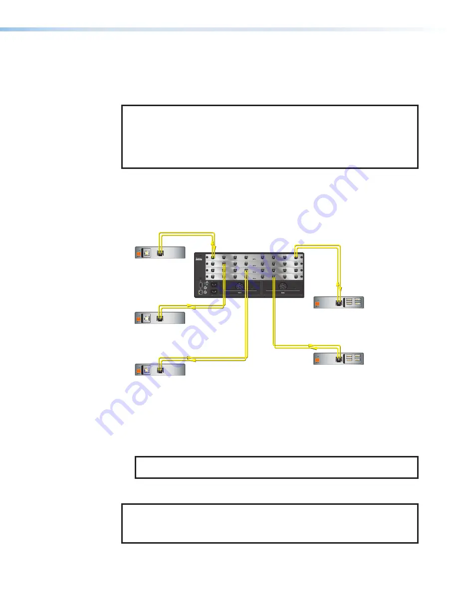
Multiple FOX T/R USB Plus Extenders can be connected to the inputs and outputs of an
Extron FOX matrix switcher to route USB signals through the switcher. This connection
enables each transmitter that is connected to a switcher input to send signals to one of the
receivers that are attached to switcher outputs.
NOTES:
•
One transmitter cannot send signals to multiple receivers at the same time and
vice-versa.
•
When using a FOX matrix or other matrix switcher with re-clockers, ensure that the
re-clockers are bypassed via SIS commands (see the switcher user guide for the
SIS commands to use).
To route USB signals through a switcher:
1.
Connect a pair of fiber optic cables from the LC SFP connector of the transmitter to a
port on a FOX matrix switcher.
2.
Connect a fiber cable pair from the LC SFP connector of the receiver to another port on
the FOX matrix switcher.
ANAHEIM, CA
RESET
REMO
TE
RS-232/RS-422
LA
N
BI-LEVEL
TRI-LEVE
L
AC
T LINK
100-240V 50/60Hz 1.2A MAX.
100-240V 50/60Hz 1.2A MAX.
REDUND
ANT
PRIMAR
Y
DISCONNECT BO
TH PO
WE
R
CORDS BEFORE SER
VICING
SWITCH
REFERENCE
PRIMARY POWER SUPPLY
REDUNDANT POWER SUPPLY
1 -
8
9 - 16
17 - 24
25 - 32
OUT
IN
A
OUT
IN
D
OUT
IN
C
OUT
IN
B
OUT
IN
E
OUT
IN
H
OUT
IN
G
OUT
IN
F
OUT
IN
A
OUT
IN
D
OUT
IN
C
OUT
IN
B
OUT
IN
E
OUT
IN
H
OUT
IN
G
OUT
IN
F
OUT
IN
A
OUT
IN
D
OUT
IN
C
OUT
IN
B
OUT
IN
E
OUT
IN
H
OUT
IN
G
OUT
IN
F
OUT
IN
A
OUT
IN
D
OUT
IN
C
OUT
IN
B
OUT
IN
E
OUT
IN
H
OUT
IN
G
OUT
IN
F
HOST
POWER
12V
1.0A MAX
INPUT
OPTICAL
Rx
Tx
HOST
POWER
12V
1.0A MAX
INPUT
OPTICAL
Rx
Tx
HOST
POWER
12V
1.0A MAX
INPUT
OPTICAL
Rx
Tx
1
2
3
4
OUTPUT
S
OPTICAL
Rx
Tx
POWER
12V
1.0A MAX
1
2
3
4
OUTPUT
S
OPTICAL
Rx
Tx
POWER
12V
1.0A MAX
FOX USB
Extender Plus
Receiver
FOX USB
Extender Plus
Transmitter
FOX USB
Extender Plus
Receiver
FOX USB
Extender Plus
Transmitter
FOX USB
Extender Plus
Transmitter
FOX Matrix 3200
Modular Fiber Optic
Matrix Switcher
Figure 11.
Example of FOX USB Plus Transmitters and Receivers Connected
to a FOX Matrix Switcher
3.
Tie the switcher input connected to the transmitter to the output to which the receiver is
connected (see the switcher user guide for the procedure to create ties).
4.
Tie the input connected to the receiver to the output connected to the transmitter.
NOTE:
Only one USB Plus transmitter and one USB Plus receiver can be tied
together via the switcher.
5.
If desired, repeat steps 1 through 3 to connect additional transmitters and receivers to
the switcher.
NOTE:
The amount of time a computer takes to enumerate and recognize a peripheral
device in a USB switching environment varies. Enumeration and switch times are
dependent on the host PC, operating system, and USB drivers associated with the
peripheral connected to the receiver.
FOX T/R USB Extender Plus • Installation and Operation
15
Summary of Contents for 60-1474-11
Page 2: ......


