


AXP 64 C AT • Installation
6
Installation
This section describes the front and rear panel features and the rear panel connections. It
also provides procedures for installing the Dante Controller and DSP Configurator software.
The following topics are discussed:
•
•
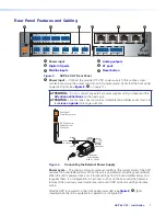
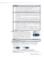
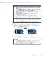
Rear Panel Features and Cabling
•
•
Connecting the AXP 64 C AT to a Network
•
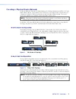
Creating a Physical Dante Network
•
•
System Configuration
The AXP 64 C AT does not have physical controls for configuration or operation. These are
accomplished using a computer running Windows
®
10
®
or later and the DSP Configurator
software (available at
), or by SIS commands using Extron DataViewer
(also available from the Extron Website).
Dante Controller for Windows from Audinate is required to select and route Dante transmit
and receive channels to all connected Dante-compatible devices (see
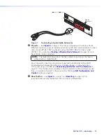
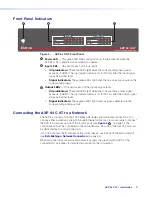
on page 23). The AXP 64 C AT has front and rear panel
operational indicators and a rear panel reset button for hardware resets
page 15.
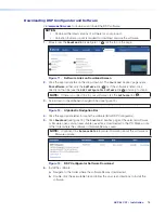
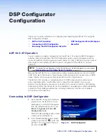
You can fully configure the AXP 64 C AT using the DSP Configurator software. When first
launched, the DSP Configurator opens a blank configuration with no processing defined. All
gain stages are muted and set to Unity (0 dB) gain.
The AXP 64 C AT provides a comprehensive set of DSP processing tools. Use the filter tools
to shape the tonal quality of your microphones or EQ the room to compensate for acoustic
gain. Use the dynamics processors for level control or system protection. Input and output
gain stages provide metering in decibels relative to full scale (dBFS) to assist in configuration
of the device for optimal operation. Optimal operating levels are close to 0 dBFS (0 dB “full
scale” on the input or output meters) without exceeding that level. Levels above 0 dBFS
cause clipping, which is always audible on a digital device.
Summary of Contents for AXP 64 C AT
Page 6: ......


