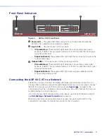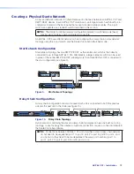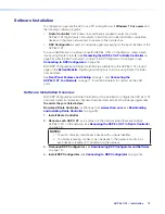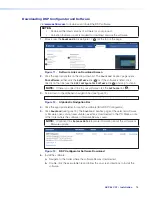
AXP 64 C AT • Installation
7
Rear Panel Features and Cabling
A
A
A
B
B
B
D
D
D
E
E
E
AXP 64 C AT
RESET
1
1
1
IN G
POWER
12V
1.0A MAX
01 02
2
3
4
I/O
INPUTS
OUTPUTS
AT
2
IN G 01 02
3
IN G 01 02
4
IN G 01 02
2
3
4
5
6
1
2
3
4
C
C
C
F
F
F
A
D
B
E
C
F
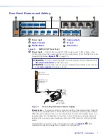
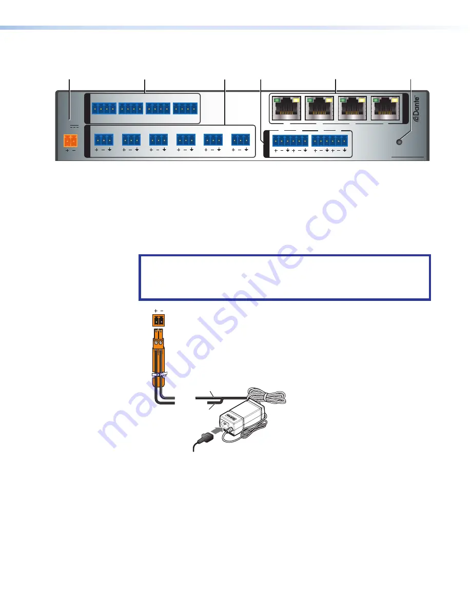
Figure 3.
AXP 64 C AT Rear Panel
A
Power input
— Connect the provided 12 VDC power supply to this captive screw
connector and plug the power cord into an AC power source. Verify that the front panel
power LED lights (see
,
A
, on page 11).
ATTENTION:
Do not connect any external power supplies until you have read the
on the next page.
ATTENTION :
Ne branchez pas de sources d’alimentation externes avant d’avoir lu
les
Rear Panel
Power Receptacle
DC Power Cord
Captive Screw
Connector
Ground
all devices.
External
Power Supply
12 VDC, 1.5 A max.
– Return
+12 VDC input
Ridged
Smooth
1A MA
X
100-240V 50-60Hz
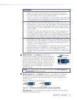
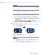
Figure 4.
Connecting the External Power Supply
Power cycle
— The mixing and audio processor settings (the current state) of the AXP
are saved in nonvolatile memory. When the unit is powered off, all settings are retained.
When the unit is powered back on, it recalls settings from the nonvolatile memory and
reapplies them. If a configuration is in process but has not been saved when power is
removed, the previously saved audio level and audio DSP processor settings become
active.
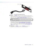
After the AXP is powered on, the front panel power LED (see
A
) lights
steadily when the unit is available for operation or configuration.
3
4
Summary of Contents for AXP 64 C AT
Page 6: ......


