
AXP 64 C AT • Installation
9
ATTENTION:
•
Condenser microphones require phantom power. Dynamic microphones
do
not
require power.
•
Les microphones électrostatiques nécessitent une alimentation fantôme. Les
microphones dynamiques n’ont pas besoin d’alimentation.
•
Never set an unbalanced dynamic microphone to +48 V. Doing so may
damage the microphone.
•
Ne réglez jamais un microphone dynamique asymétrique à +48 V. Cela
pourrait endommager le micro.
•
For condenser microphones, verify it safely operates at
+
48 VDC.
•
Pour les microphones électrostatiques, vérifiez qu’ils fonctionnent bien à
+48 Vcc.
•
When a line level source is connected, be certain the +48 V phantom power is
off (cleared).
•
Lorsqu’une source de niveau ligne est connectée, soyez certain que
l’alimentation fantôme +48 V est débranchée (enlevée).
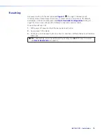
D
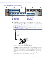
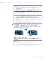
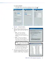
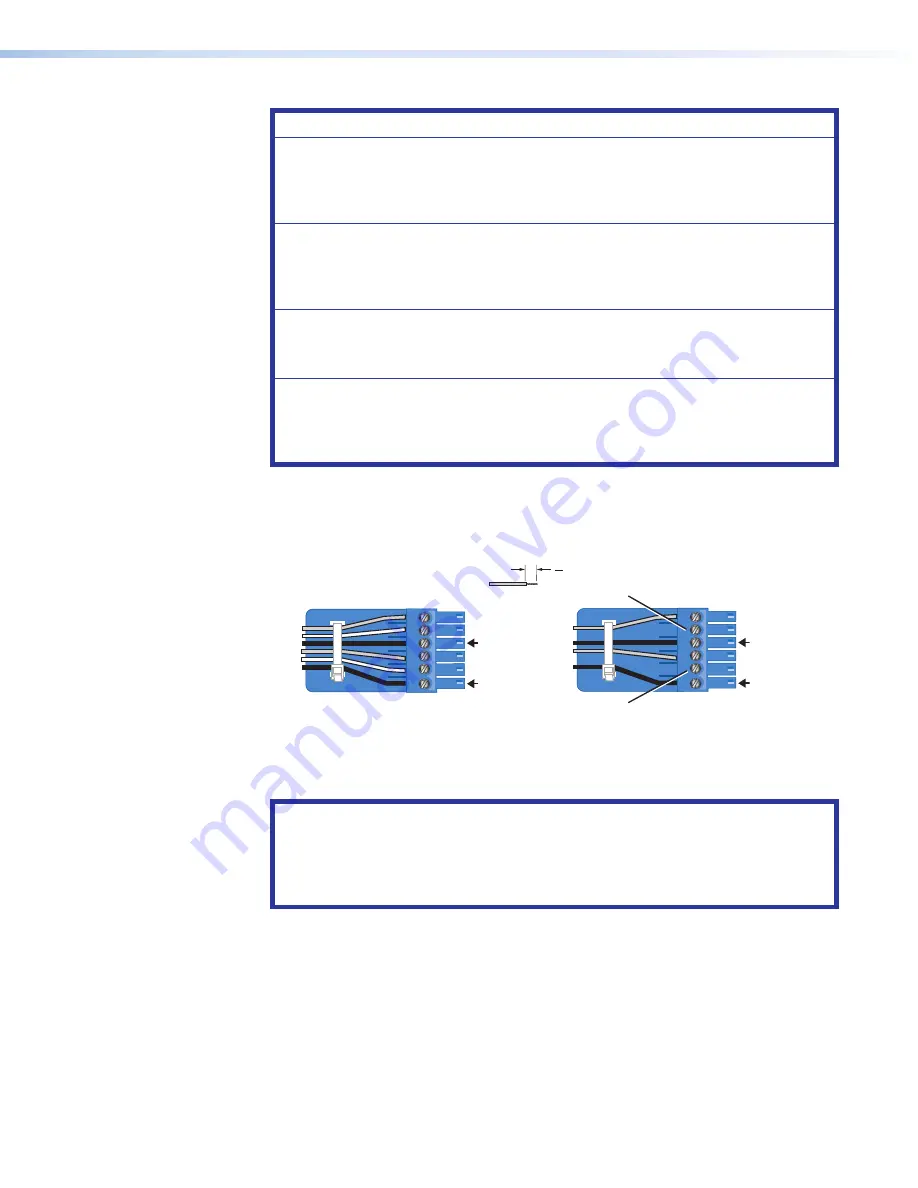
Analog outputs
— Audio outputs 1 through 4 are on two 3.5 mm, 6-pole captive
screw connectors (see
on page 7). Connect up to four balanced or
unbalanced mono line level or two stereo outputs to these two 6-pole 3.5 mm captive
screw connectors. Wire as shown in figure 6.
Do not tin the wires!
(5 mm) MAX.
3 "
16
Balanced Output
Unbalanced Output
+
–
+
–
Tip
Ring
Tip
Ring
Sleeves
Tip
No Ground Here
No Ground Here
Tip
Sleeves
Sleeves
Sleeves
+
–
+
–
Figure 6.
Wiring for Analog Output
Alternatively, 3-pole or 5-pole connectors can be used (see
for
an example).
ATTENTION:
•
For unbalanced audio outputs, connect the sleeves to the ground contact.
DO NOT connect the sleeves to the negative (-) contacts.
•
Pour l’audio asymétrique, connectez les manchons au contact au sol. Ne
PAS connecter les manchons aux contacts négatifs (–).
6
Summary of Contents for AXP 64 C AT
Page 6: ......


