AXP 64 C AT • Installation
10
DO NOT
Connect Here
AXP
64 C
AT
RES
ET
1
1
1
IN
G
PO
WER
12V
X.XA
MAX
01
02
2
3
4
I/
O
INPUTS
OUTPUTS
AT
2
IN
G
01
02
3
IN
G
01 0
2
4
IN
G
01
02
2
3
4
5
6
1
2
3
4
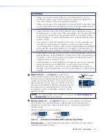
5-pole CSR
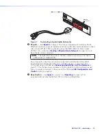
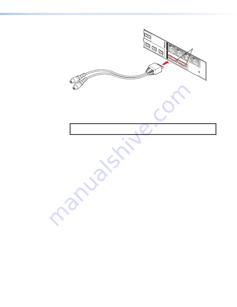
Figure 7.
Connecting a 5-pole Audio Connector
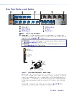
E
AT ports
— (see
on page 7) This four-port Gigabit switch with four RJ-45
Ethernet connectors supports digital audio transport (AT) and communications. Connect
one or more AXP 64 C ATs to a device such as the DMP 128 AT to form a larger
AXP 64 C AT system (see
Creating a Physical Dante Network
56 channels can be connected.
NOTE:
The digital and analog input channel is shared for each input. An input is
either analog or digital (Dante).
Any of these AT connectors can also be connected to an Ethernet LAN or WAN.
Communication between the AXP and a controlling device or computer is via a
TCP socket using port 4333 (see
Connecting the AXP 64 C AT to a Network
page 11). This connection also enables control of the AXP via SIS commands issued
from a computer connected to the same LAN or WAN (see
F
Reset button
on page 15) This
recessed button returns the AXP 64 C AT to its factory default state.
7
Summary of Contents for AXP 64 C AT
Page 6: ......

