
AXP 64 C AT • Installation
12
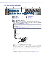
Creating a Physical Dante Network
A physical network is required to share Dante audio channels between an AXP 64 C AT and
DMP 128 AT devices. Each AXP 64 C AT contains a 4-port Gigabit switch with four RJ-45
connectors located on the back panel that accept standard network cables. The 4-port
switch can operate as a standard switch described in this section.
NOTE:
The Dante Controller network configuration defaults to switched mode (basic)
making star and daisy-chain configurations possible.
An AXP 64 C AT-based Dante network can be configured in a daisy-chain or star network
topology using the 4-port switch and the Dante Controller in Switched mode.
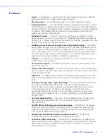
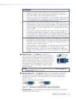
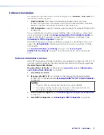
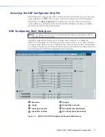
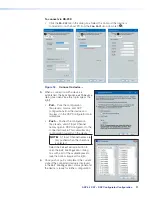
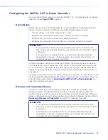
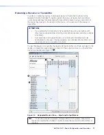
Star Network Configuration
Star network topology has one DMP 128 C AT as the central unit, which is then directly
connected to up to three AXP 64 C ATs. Alternatively, a larger network switch can be used
in place of the central DMP 128 C AT, allowing more than three AXP 64 C ATs connected in
the star configuration (see figure 9).
100-240V ~ --A MAX
50/60 Hz
LAN
EXP
RS-232
Tx Rx G
RESET
MIC +48V
5
6
7
8
1
2
3
4
8
4
1
1 2 3 4 5 G
6
1
2
3
4
7 8 9 10 G
11 12 13 14 15 G
16 17 18 19 20 G
2
3
4
5
6
7
8
9
10
11
12
7
3
6
2
5
1
MIC/LINE INPUT
S
OUTPUT
S
DIGITAL I/
O
REMOTE
AT
DMP 128 C AT
AXP 64 C AT
AXP 64 C AT
RESET
1
1
1
IN G
POWER
12V
X.XA MAX
01 02
2
3
4
I/O
INPUT
S
OUTPUT
S
AT
2
IN G 01 02
3
IN G 01 02
4
IN G 01 02
2
3
4
5
6
1
2
3
4
AXP 64 C AT
AXP 64 C AT
RESET
1
1
1
IN G
POWER
12V
X.XA MAX
01 02
2
3
4
I/O
INPUTS
OUTPUT
S
AT
2
IN G 01 02
3
IN G 01 02
4
IN G 01 02
2
3
4
5
6
1
2
3
4
DMP 128 C AT
AXP 64 C AT
AXP 64 C AT
RESET
1
1
1
IN G
POWER
12V
X.XA MAX
01 02
2
3
4
I/O
INPUT
S
OUTPUT
S
AT
2
IN G 01 02
3
IN G 01 02
4
IN G 01 02
2
3
4
5
6
1
2
3
4
Figure 9.
Star Network Topology
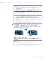
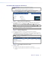
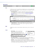
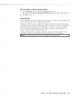
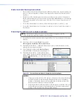
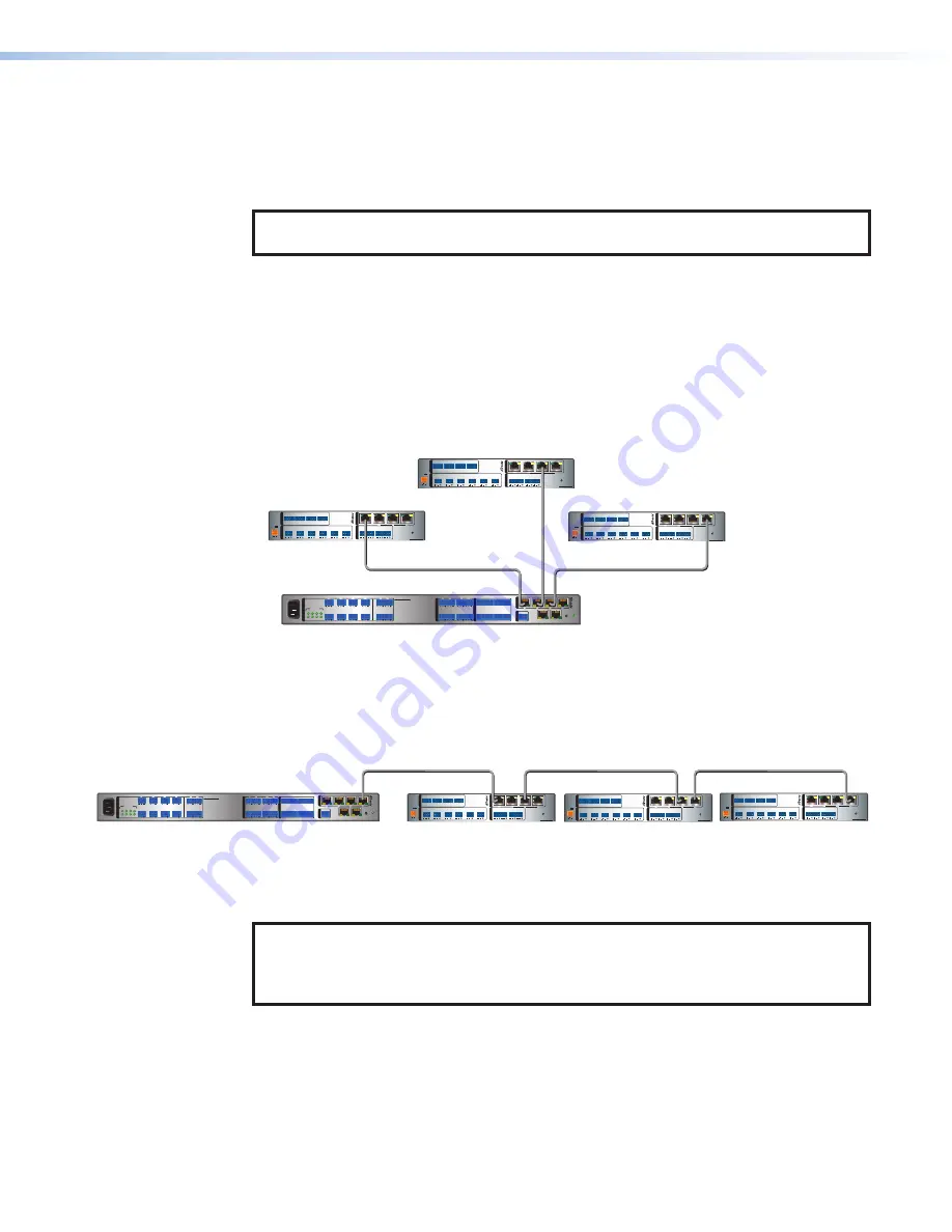
Daisy Chain Configuration
A daisy chain configuration can also be used. Each unit is connected to both the previous
unit and the next unit in the chain (see figure 10).
DMP 128 AT
100-240V ~ --A MAX
50/60 Hz
LAN
EXP
RS-232
Tx Rx G
RESET
MIC +48V
5
6
7
8
1
2
3
4
8
4
1
1 2 3 4 5 G
6
1
2
3
4
7 8 9 10 G
11 12 13 14 15 G
16 17 18 19 20 G
2
3
4
5
6
7
8
9
10
11
12
7
3
6
2
5
1
MIC/LINE INPUTS
OUTPUT
S
DIGITAL I/
O
REMOTE
AT
DMP 128 C AT
AXP 64 C AT #1
AXP 64 C AT #2
AXP 64 C AT #3
AXP 64 C AT
RESET
1
1
1
IN G
POWER
12V
X.XA MAX
01 02
2
3
4
I/O
INPUT
S
OUTPUT
S
AT
2
IN G 01 02
3
IN G 01 02
4
IN G 01 02
2
3
4
5
6
1
2
3
4
AXP 64 C AT
RESET
1
1
1
IN G
POWER
12V
X.XA MAX
01 02
2
3
4
I/O
INPUT
S
OUTPUT
S
AT
2
IN G 01 02
3
IN G 01 02
4
IN G 01 02
2
3
4
5
6
1
2
3
4
AXP 64 C AT
RESET
1
1
1
IN G
POWER
12V
X.XA MAX
01 02
2
3
4
I/O
INPUT
S
OUTPUT
S
AT
2
IN G 01 02
3
IN G 01 02
4
IN G 01 02
2
3
4
5
6
1
2
3
4
Figure 10.
Daisy Chain Topology
Hybrid versions combining the star and daisy chain topologies can also be built, but a ring
topology, or any topology that creates a duplicate connection, causes a connection failure in
the Dante Controller software.
NOTE:
Connections between AXP 64 C AT ports in either a star or daisy chain network
do not need to be sequential (port 1 to port 2, port 2 to port 3, port 3 to port 4, and
so on), nor do they need to be made between the same port numbers (port 1 to
port 1, port 2 to port 2, port 3 to port 3, and so on).
9
10
Summary of Contents for AXP 64 C AT
Page 6: ......


