background image


8

Cable Cubby 1252 MS • Installation Guide (Continued)

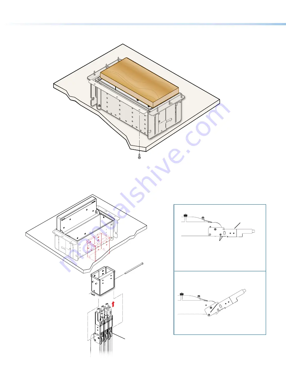
Step 2 — Install trim brackets

If there is a gap, front and back, between the underside of the table and the Cable Cubby frame, install the trim brackets as follows:

Hold the trim bracket 

against the underside of the 

table, flush against the Cable 

Cubby and centered on the unit. 

Mark the three mounting holes. 

Drill 1/8 inch (3 mm) diameter pilot holes,

1/2 inch (12.7 mm) deep.

Secure the trim bracket to the table using the 

provided #8 wood screws.

Repeat      through      on the opposite of the Cable 

Cubby.

2

3
4

1

1

3

Installing Optional Accessories

Installing Retractors

For horizontal or angular retractor mounting, see the information at right, then follow the steps below.

Insert the pin through the 

Retractor mounting hole

on  the side of the

Cable Cubby and

Retractor assembly.

Secure the clip 

on the pin.

Insert Retractors into 

the Retractor bracket.

Secure the locking screw 

on each Retractor. Do not 

overtighten.

2

1

4

3

Pin

Clip

Extr

on

Angular Mounting

Remove the enclosure screws as shown above, then follow
this step: 

Horizontal Mounting


Cable Release

Assembly

Move the cable release assembly upward until 

the angular mounting hole is visible. Reinstall the 

enclosure screws in this hole (both sides).

Remove two enclosure screws 

(one on each side) from this position. 

Then, mount the Retractors as shown 

at left.

Cable Release

Assembly

See the 

Cable Retractor Series Setup Guide

, available on

the Extron website, for additional steps.

Remove two enclosure screws

(one on each side) from this position.

Then, mount the Retractors as shown

at left.

Move the cable release assembly upward until 

the angular mounting hole is visible. Reinstall the 

enclosure screws in this hole (both sides).

Summary of Contents for Cable Cubby 1252 MS

Page 1: ...ting the installation Ensure that the planned installation complies with national and local building and electrical codes Ensure that the planned installation complies with the Americans with Disabilities Act or other accessibility requirements Check all parts and equipment before installation Ensure that all parts are present in the kit Ensure that necessary tools and equipment are available for ...

Page 2: ...e table surface see figure 1 on page 3 If total lid thickness is thinner than the table surface see figure 2 on page 3 Les dimensions correctes pour la découpe dans la surface de table dépendent de l épaisseur de votre couvercle Si l épaisseur totale du couvercle est égale ou plus importante que la surface de la table regardez la figure 1 Si l épaisseur totale du couvercle est moins importante que...

Page 3: ... 50 8 mm 2 00 50 8 mm 0 63 16 0 mm 10 50 266 7 mm 0 63 15 9 mm R 0 25 6 3 mm Cut Dimensions Thicker table surface Width 8 81 inches 223 8 mm Depth 5 25 inches 133 3 mm Corner 0 25 inch radius 6 3 mm Cut Dimensions Thinner table surface Width 9 5 inches 241 3 mm Depth 5 25 inches 133 3 mm Corner 0 25 inch radius 6 3 mm A B Figure 3 Enclosure Dimensions and Mounting Hole Locations 2 Mark and pre dri...

Page 4: ...vity brackets using four of the provided 4 40 module screws Use a screwdriver to tighten the screws 3 1 2 Insert cables through the bottom of the connectivity bracket Connect cables to the AAP modules NOTE After assembling the module proceed to Step 2 Install the Modules on page 5 Option 2 Cable pass through module Secure the grommet plate on the connectivity bracket using four of the provided 4 4...

Page 5: ... the Modules Determine where the connectivity modules and power module will be installed in the Cable Cubby The modules may be installed on the left or right side of the enclosure and at various heights NOTE Ensure that there is enough room above the modules for the Cable Cubby lid to close completely Extron Extron 12 5V 12 A MAX TO TA L Secure the modules using four of the provided 6 32 pan head ...

Page 6: ...on 2 3 Mounting the Cable Cubby in the Table 1 See the dimension on figure 3 on page 3 for the mounting hole locations OR have an assistant hold the Cable Cubby against the underside of the mounting surface 2 Install the screws in the two center pre drilled mounting holes on each side leaving 1 8 inch 4 mm of the screw head exposed 3 Use the two center slotted mounting holes on the mounting bracke...

Page 7: ...but do not remove the wing bolts two on each side just enough to allow the Cable Cubby to slide up and down in the brackets Raise the unit up or down until the lid is flush with the table top surface Use an assistant if necessary 1 Firmly tighten the wing bolts 3 2 NOTE If the lid is thinner than the table surface it may be necessary to relocate the wing bolts to the bottom position of the Cable C...

Page 8: ...g hole on the side of the Cable Cubby and Retractor assembly Secure the clip on the pin Insert Retractors into the Retractor bracket Secure the locking screw on each Retractor Do not overtighten 2 1 4 3 Pin Clip Extron Angular Mounting Remove the enclosure screws as shown above then follow this step Horizontal Mounting Cable Release Assembly Move the cable release assembly upward until the angular...

Page 9: ...K 155 see the PMK 155 Installation Guide 1 Install the two supplied Allen bolts from the PMK 155 kit to the shelf leaving approximately 1 8 inch 4 mm protruding 2 Slide the shelf sideways horizontally onto the Cable Cubby mounting bracket from the front of the enclosure on either the left or right side until the shelf drops into the slot in the bracket 3 Tighten the bolts with a 4 mm Allen wrench ...

Page 10: ...Connecting Cables For cable pass through applications allow at least 36 inches 0 9 m of cable loop for each cable Connect cables to the AV system and connect the AC power cord Using zip ties secure cables to the holes on the bottom of the Cable Cubby 1 2 3 1 Extron ...

Page 11: ...tor 7 14 181 4 mm 21 66 550 1 mm 23 33 592 6 mm 0 30 7 6 mm 13 63 346 2 mm 9 00 228 6 mm 10 14 257 6 mm 26 85 682 1 mm 0 20 5 1 mm 29 33 745 0 mm 19 63 498 6 mm 9 0 228 6 mm Figure 4 Retractor Dimensions with Cable Cubby 1252 MS ...

Page 12: ...lation Check all parts and equipment before installation Preparing the Table Determine the best location for the enclosure Determine cutout hole size based on lid thickness page 3 Cut the hole in the table and pre drill mounting locations page 3 Fabricate Cable Cubby lid page 3 Preparing the Cable Cubby Assemble Connectivity Modules page 4 Install the Modules page 5 Mount the Lid onto the Cable Cu...

Reviews: