Extron electronics DVI DA Plus Series, User Manual
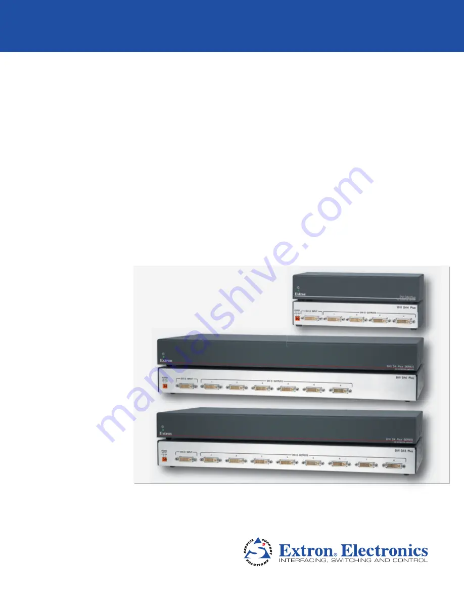
The Extron Electronics DVI DA Plus Series offers high-quality signal distribution for digital video and audio in various applications. To get the most out of your device, refer to the comprehensive User Manual available for free download at 88.208.23.73:8080. Explore advanced features and settings effortlessly with this detailed manual.
Share
Download


Reviews:
No comments
Related manuals for DVI DA Plus Series

C320
Brand: NAD Pages: 3

C320
Brand: NAD Pages: 36

A200
Brand: Zeck Audio Pages: 6

V70
Brand: Octave Pages: 23

3100
Brand: NAD Pages: 2

A 1000
Brand: E&I Pages: 13

319
Brand: NAD Pages: 2

66
Brand: QUAD Pages: 17

319
Brand: NAD Pages: 39

77
Brand: QUAD Pages: 16

90
Brand: NAD Pages: 7

CS Series
Brand: JBL Pages: 20

AP2500
Brand: Harman Kardon Pages: 8

3130
Brand: NAD Pages: 8

3130
Brand: NAD Pages: 20

3150
Brand: NAD Pages: 8

2700
Brand: NAD Pages: 2

EP Series
Brand: D.A.S. Pages: 15


