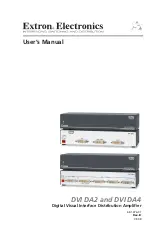
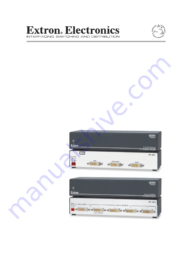
background image

User’s Manual

Digital Visual Interface Distribution Amplifier

68-1376-01

Rev. B

08 08

DVI DA2 and DVI DA4

Summary of Contents for DVI DA2

Page 1: ...User s Manual Digital Visual Interface Distribution Amplifier 68 1376 01 Rev B 08 08 DVI DA2 and DVI DA4 ...

Page 2: ...faufmerksam machen daß im Inneren des Gehäuses dieses ProduktesgefährlicheSpannungen dienichtisoliert sind und die einen elektrischen Schock verursachen können herrschen Achtung Lesen der Anleitungen Bevor Sie das Gerät zum ersten Mal verwenden sollten Sie alle Sicherheits und Bedienungsanleitungen genau durchlesen und verstehen Aufbewahren der Anleitungen Die Hinweise zur elektrischen Sicherheit ...

Page 3: ...e pursuant to part 15 of the FCC Rules Operation is subject to the following two conditions 1 this device may not cause harmful interference and 2 this device must accept any interference received including interference that may cause undesired operation The Class A limits are designed to provide reasonable protection against harmful interference when the equipment is operated in a commercial envi...

Page 4: ......

Page 5: ... 2 DVI Cable Connections Connect a DVI cable from the Input connector to the video source device Connect a DVI cable from the Local Output connector to the desired local output device Connect a DVI cable s from the Output connector s to the desired display device s 12 V 0 4 A MA X PO WER IN PU T LO CAL OUTP UT OUTP UT DVI DA2 SU PP OR TS DV I D ON LY PC Local Output Monitor LCD Flat Panel Display ...

Page 6: ... s power receptacle Connect the 12 VDC power cord to an AC power outlet 12V 0 4A MAX POWER Power Receptacle DC Power Cord Captive Screw Connector AC Power Cord Ground 12 VDC External Power Supply 12 VDC 1 A Step 4 Applying Power Power on the local monitor Power on the display device s Power on the source input device N Output 1 is used as a DDC reference and must be connected to the distribution a...

Page 7: ...Installation and Operation 2 1 Installation Overview 2 2 Mounting the Distribution Amplifier 2 2 Tabletop placement 2 2 Rack mounting 2 2 UL guidelines for rack mounting 2 2 Rack mounting procedure 2 3 Under desk mounting 2 4 Front Panel Features 2 6 Rear Panel Features 2 7 Cable Connections 2 8 DVI Connections 2 8 DVI connector pin assignments 2 9 Power Connections 2 10 Operation 2 11 Troubleshoo...

Page 8: ...ii DVI DA2 and DVI DA4 Table of Contents Table of Contents cont d ...

Page 9: ...DVI DA2 and DVI DA4 1 Chapter One Introduction About this manual About the DVI DA2 and DVI DA4 DVI DA2 and DVI DA4 Features ...

Page 10: ...r operation of both models About the DVI DA2 and DVI DA4 These Digital Visual Interface DVI Distribution Amplifiers DAs have one input and either two DVI DA2 or four DVI DA4 outputs Both distribution amplifiers accept one single link DVI D input and drive two DVI DA2 or four DVI DA4 single link DVI D output signals In both models Output 1 is used for Digital Display Channel DDC reference 12 V 0 4A...

Page 11: ...al monitor Output 1 is used as a DDC reference and is labeled Local Output for easy reference The video source uses the bidirectonal DDC to communicate with the local monitor which allows the source to determine the resolution and refresh rate of the signal that it sends N Since output 1 is used as the reference all other display devices must be capable of handling resolutions equal to or greater ...

Page 12: ...DVI DA2 and DVI DA4 Introduction Introduction cont d 1 4 ...

Page 13: ...VI DA2 and DVI DA4 2 Chapter Two Installation and Operation Installation Overview Mounting the Distribution Amplifier Front Panel Features Rear Panel Features Cable Connections Operation Troubleshooting ...

Page 14: ...nit and place it in any convenient location Rack mounting UL guidelines for rack mounting The following Underwriters Laboratories UL guidelines are relevant to the safe installation of these products in a rack 1 Elevated operating ambient temperature If the unit is installed in a closed or multi unit rack assembly the operating ambient temperature of the rack environment may be greater than room a...

Page 15: ...90 10 1U 6 rack shelf kit RSB 126 part 60 604 11 1U 6 basic rack shelf RSU 129 part 60 190 01 1U 9 5 rack shelf kit RSB 129 part 60 604 02 1U 9 5 basic rack shelf Use 2 mounting holes on opposite corners 2 4 40 x 3 16 Screws 1U Universal Rack Shelf Front false faceplate uses 2 screws 1 2 Rack Width Front False Faceplate Rack mounting the DVI DA2 or DVI DA4 To mount the distribution amplifier on a ...

Page 16: ...nting brackets to the unit with the four provided 4 40 x 3 16 screws 3 Hold the unit with the mounting brackets attached under the furniture where it will be secured Mark the position of the holes on the underside of the furniture 4 In the marked positions drill four pilot holes 3 32 2 mm in diameter and 1 4 6 mm deep 5 Insert the four provided wood screws into the pilot holes and tighten until ap...

Page 17: ...DVI DA2 and DVI DA4 Installation and Operation 2 5 ...

Page 18: ...tion Installation and Operation cont d 2 6 Front Panel Features DVI DA SERIES DVI DISTRIBUTION AMPLIFIER 1 Front panel features a LED indicator On both the DVI DA2 and DVI DA4 the LED indicator illuminates green when the unit is receiving power ...

Page 19: ...s equalized to ensure integrity N Although DVI I dual link connectors are used the DVI DA2 and DVI DA4 are only compatible with single link DVI D video signals c Output Connectors Connect up to four DVI D outputs to display devices using the female DVI connectors d Local Monitor connector Output 1 Local Monitor is used as a DDC reference For the input device to provide a signal at the correct reso...

Page 20: ...r 1080p 60 Hz Input EQ conditions input signals to ensure the integrity of the signals delivered to the output devices 2 Use DVI I cables to connect up to four display devices To output a HDMI signal use a HDMI to DVI adapter such as the Extron HDMIF DVIDM female HDMI to male DVI D adapter 26 616 01 N The actual signal transmission distance can vary and depends on signal resolution cable quality g...

Page 21: ...und Analog vertical sync TMDS clock Hot plug detect TMDS data 0 TMDS data 0 TMDS data 4 TMDS data 4 TMDS data 3 TMDS data 3 TMDS data 5 TMDS data 5 TMDS data 2 4 shield TMDS data 1 3 shield TMDS data 0 5 shield TMDS clock shield Pin Pin Signal Signal 2 9 10 17 4 12 20 5 13 21 6 14 22 7 15 23 8 16 24 18 3 11 19 C1 C3 C5 C2 C4 Unused Unused Unused Unused Unused Three rows of 8 pins and two contacts ...

Page 22: ...r receptacle N Ensure the cable is connected with the correct polarity Power Supply Output Cord SECTION A A Ridges Smooth A A Cable Polarity 12V 0 4A MAX POWER Power Receptacle DC Power Cord Captive Screw Connector AC Power Cord Ground 12 VDC External Power Supply 12 VDC 1 A Connecting the power supply 2 Connect the AC power cord of the power supply unit to a 110 or 220 VAC electrical source ...

Page 23: ... displays see page 2 8 4 Connect and power on the source device see page 2 8 N Output 1 LOCAL OUTPUT is used as a DDC reference and must be connected to the distribution amplifier before the source device If the source device cannot communicate with the local monitor when it is being powered on it may not be able to send a video signal or the signal may have the wrong resolution or refresh rate ...

Page 24: ...ion or refresh rate No output signal or poor quality signal Check the input and output cabling see page 2 8 DVI signals run at very high frequency and poor connections can cause degradation or loss of the signal or jitter To avoid this Use only cable that is designed for DVI signals Limit or avoid the use of adapters Display device displays a flashing black or blue screen snow or other distortion ...

Page 25: ...DVI DA2 and DVI DA4 A Appendix A Reference Information Specifications Included Parts Accessories ...

Page 26: ... DVI D or HDMI 1 main 1 local N Local output is used for DDC communications and hot plug detection DVI DA4 4 single link DVI D or HDMI Connectors 2 or 4 female DVI I depending on model General External power supply 100 VAC to 240 VAC 50 60 Hz external to 12 VDC 1A regulated Power input requirements 12 VDC 0 4 A Temperature humidity Storage 40 to 158 F 40 to 70 C 10 to 90 noncondensing Operating 32...

Page 27: ...k wide 4 4 cm H x 22 2 cm W x 7 6 cm D Depth excludes connectors Product weight 2 8 lbs 1 3 kg Shipping weight 5 lbs 3 kg Vibration ISTA 1A in carton International Safe Transit Association Regulatory Compliance Safety C tick CUL UL EMI EMC CE C tick FCC Class A ICES VCCI MTBF 30 000 hours Warranty 3 years parts and labor N All nominal levels are at 10 N Specifications are liable to change without ...

Page 28: ...mber DVID SL series 3 6 or 15 feet single link DVI D male to male patch cables 26 585 0x IN9700 series 25 35 50 or 75 feet single link DVI D male to male long distance extension cables 26 584 0x HDMIF DVIDM HDMI female to DVI D male adapter 26 616 01 MBU 125 Under desk mount kit 70 077 01 RSF 123 3 5 deep 1U rack shelf kit 60 190 20 RSB 123 3 5 deep 1U basic rack shelf 60 604 21 RSU 126 6 deep 1U ...

Page 29: ...y misuse improper handling care electrical or mechanical abuse abnormal operating conditions or non Extron authorized modification to the product If it has been determined that the product is defective please call Extron and ask for an Applications Engineer at 714 491 1500 USA 31 33 453 4040 Europe 65 6383 4400 Asia or 81 3 3511 7655 Japan to receive an RA Return Authorization number This will beg...

Page 30: ...1797 FAX Extron Europe 800 3987 6673 Inside Europe Only 31 33 453 4040 31 33 453 4050 FAX Extron Asia 800 7339 8766 Inside Asia Only 65 6383 4400 65 6383 4664 FAX Extron Japan 81 3 3511 7655 81 3 3511 7656 FAX Extron China 400 883 1568 Inside China Only 86 21 3760 1568 86 21 3760 1566 FAX Extron Dubai 971 4 2991800 971 4 2991880 FAX 2008 Extron Electronics All rights reserved ...

Reviews: