


FOX 500 DA6 • Installation and Operation
Installation and Operation, cont’d
2-6
FOX 500 DA6 • Installation and Operation
2-7
The input's audio level can be individually set via the master
receiver's front panel or RS-232 control. Refer to the
FOX 500
Tx/Rx
manual and see chapter 3, "Remote Control" in this
manual.
e
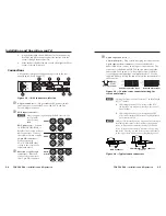
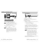
RS-232 Over Fiber port —
If you want the
FOX 500 to pass serial command signals to the
receiver(s) (for serial control of a projector, for
example), connect the host device to the DA via
the left three poles of this 5-pole captive screw
connector. See "Rear panel serial ports connection" on page
2-8 to wire this connector.
N
If you connect only one fiber optic cable (item
h
,
on the
next page), you do not receive reports from the controlled
device connected to the master receiver. To receive
responses from the controlled device, you must install two
fiber optic cables.
N
The FOX 500 can pass RS-232 commands and responses
at rates up to 38400 baud.
f
Remote RS-232 port —
For serial control of the
DA, connect a host device, such as a computer,
touch panel control, or RS-232 capable PDA, to the
DA via the left three poles of this 5-pole captive
screw connector.
See "Rear panel serial ports
connection" on page 2-8 to wire this connector.
See chapter 3, "Remote Control", for definitions of the SIS
commands (serial commands to control the DA via this
connector).
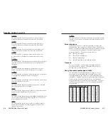
g
Alarm outputs port
— For remote monitoring
of the status of fiber optic link 2 from the
master receiver, connect a locally-constructed
or furnished device to the DA via the right two
poles of this 5-pole captive screw connector.
When the DA does not detect a light link on fiber cable
Optical 2 (optional) of output 1, it shorts pin 1 and pin 2 of
this port together.
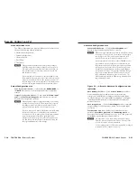
FOX 500 Tx DA6
OPTICAL
1
1
2
LINK
LINK
2
1 2*
*
NOT USED
3
1 2*
*
NOT USED
4
1 2*
*
NOT USED
5
1 2*
*
NOT USED
6
1 2*
*
NOT USED
8
8
8
8
8
8
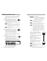
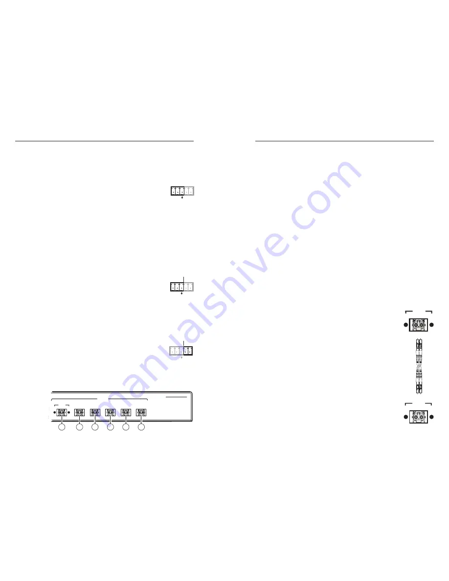
Figure 2-5 — DA’s connectors, right side
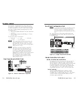
h
Fiber optic connectors and LED
—
W
These units output continuous invisible light,
which may be harmful and dangerous to the eyes;
use with caution. For additional safety, plug the
attached dust caps into the optical transceivers
when the fiber optic cable is unplugged.
N
Singlemode and multimode devices are
not
interchangeable. Ensure that you connect receiving
devices that are compatible with the DA.
N
Ensure that you use the proper fiber cable for your
DA/receiver pair. Typically, singlemode fiber has a yellow
jacket and multimode cable has an orange jacket.
N
Only one fiber optic cable, Optical 1, is required for
video, audio, and serial command transmission. But,
if you connect only one fiber optic cable, you do
not
receive RS-232 communications from the controlled
device connected to the master receiver, and there is
reduced
RS-232 command and Windows control program
functionality on the receiver. To receive responses
from the master receiver and for full functionality,
you must install both fiber optic cables between the
DA and the master receiver.
Optical 1
— For all one-way video, audio,
and serial communications from the DA to
the receiver, connect a fiber optic cable to the
Optical 1 LC connector.
Connect the free end of this fiber optic cable to
the Optical 1 connector on the receiver
or other
compatible Extron device
.
Optical 2
— For all one-way serial
communications from the master receiver
to the DA, connect a fiber optic cable to the
Optical 2 LC connector.
Connect the free end of this fiber optic cable
to the Optical 2 connector on the
receiver
connected to DA output 1 or to any other
compatible device
.
N
Optical 2 is functional only for output 1.
Link 1 and Link 2 LEDs
— When lit, the link
is active (light is received).
N
The Link 1 and Link 2 LEDs are present only for output 1.
RS-232
OVER FIBER
Tx Rx
NA
REMOTE
RS-232
ALARM
Tx Rx
1 2
REMOTE
RS-232
ALARM
Tx Rx
1 2
OPTICAL
1 2*
*
OPTIONAL FOR
RETURN DATA
LINK
LINK
OPTICAL
2* 1
*
OPTIONAL FOR
RETURN DATA
LINK
LINK


